Method of recycling spent nuclear fuel

a nuclear fuel and waste technology, applied in nuclear energy generation, reactor fuel elements, climate sustainability, etc., can solve the problems of increasing the volume of lrw, reducing the degree of irradiation of lrw, and reducing the extent of sublimation of cesium compounds, so as to increase the extent of tritium removal and reduce the extent of cesium compounds

Inactive Publication Date: 2015-09-29
FEDERAL INITARY ENTERPRISE MINING & CHEM COMBINE
View PDF10 Cites 0 Cited by
  • Summary
  • Abstract
  • Description
  • Claims
  • Application Information

AI Technical Summary

Benefits of technology

[0009]Therefore, the need exists of increasing the extent of the removal of tritium from the fuel composition and decreasing the extent of the sublimation of cesium compounds using air with the addition of carbon dioxide and water vapors.

Problems solved by technology

However, failure to purposefully remove tritium at the initial stage of recycling SNF, prior to its dissolution, leads to spreading tritium practically into all of the aqueous technological products of the process and thus complicates recycling liquid radioactive waste (LRW) to a great extent resulting in the increase of the volume of LRW.
This creates additional problems relating to making the reactor, and handling fission products as their compounds (comprising cesium, silver, ruthenium, iodine, technetium, antimony, etc.) start to evaporate at high temperature and condense in various parts of equipment.
This, in its turn, necessitates performing repeatable liquid decontamination of the equipment which results in the formation of additional hot LRW.
The prototype's disadvantage lies in an inadequate extent of tritium stripping from the SNF and in rather high degree of cesium sublimation and further carrying it over that poses additional problems associated with decontaminating and redistributing hot fission products throughout the stages of SNF recycling.

Method used


Image

  • Method of recycling spent nuclear fuel
  • Method of recycling spent nuclear fuel

Examples


Embodiment Construction

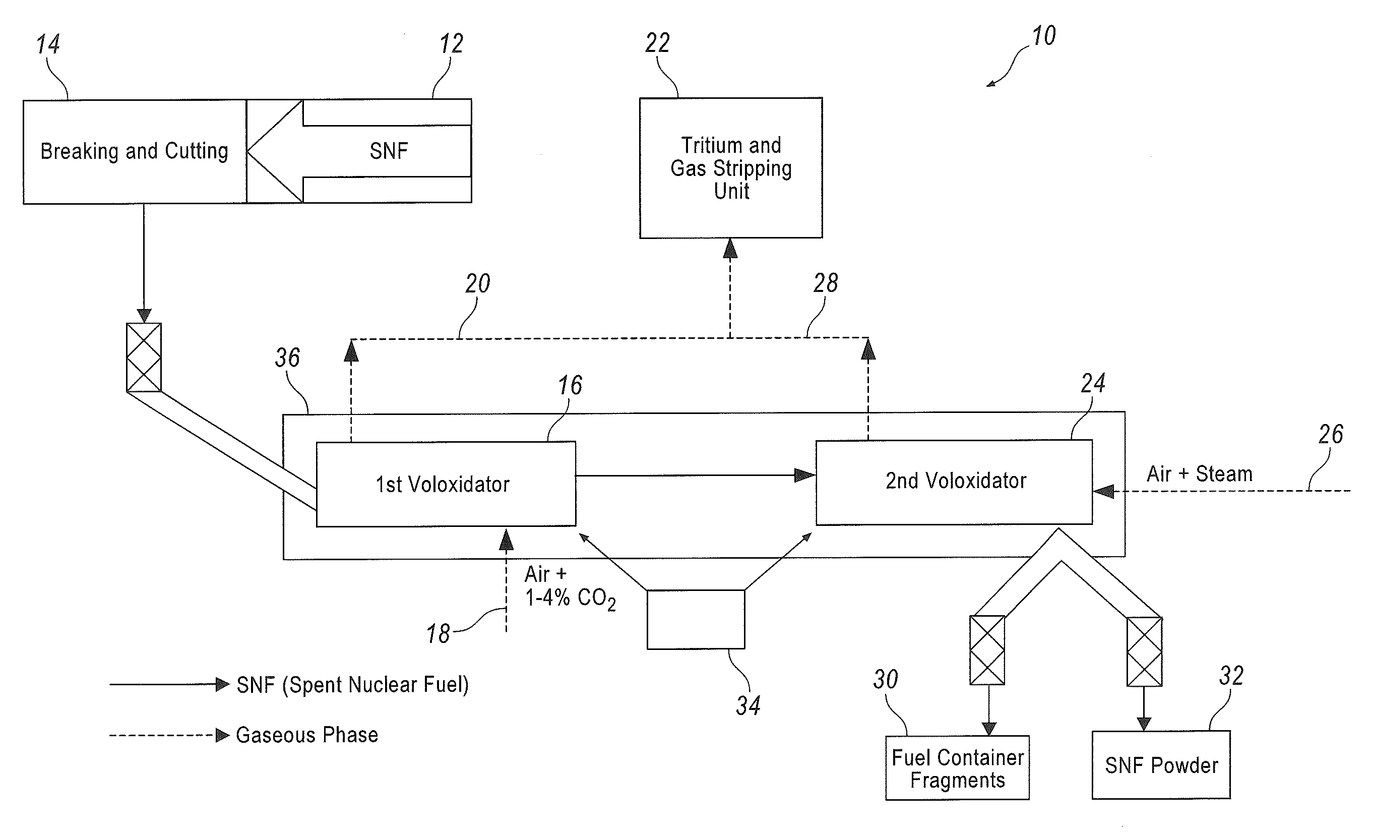
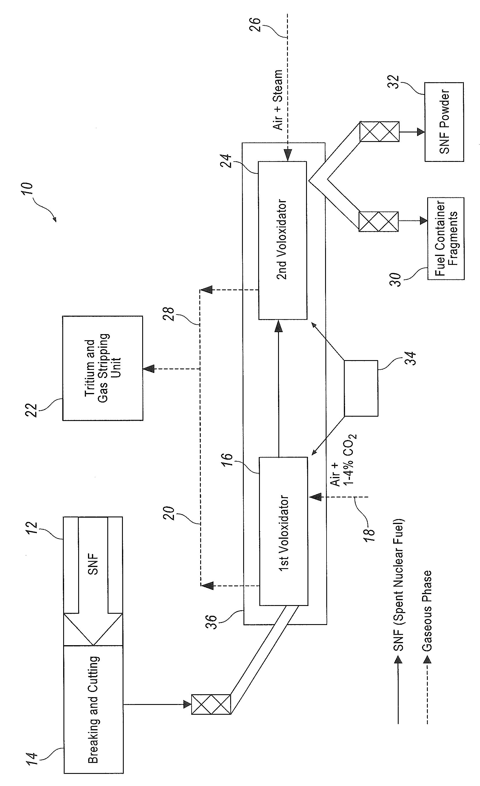
[0012]According to modern refined thermodynamic calculations, tritium is present in SNF in three chemical species: T2, T2O (HTO) and CsOT. As will be shown below, this determines the essence of the method being described herein, particularly oxidative recrystallization (voloxidation) of SNF.

[0013]Referring now to the FIGURE showing an installation 10 for the realization of the method in question, SNF 12 subject to recycling arrives to a unit 14 for breaking and cutting spent fuel elements and their jackets (containers). The fragmented SNF enters a 1st reaction chamber (voloxidator) 16. Taking place in it at the first phase of SNF recycling is breaking uranium dioxide structure, oxidizing tritium to tritium water, and removing the main body of tritium including that contained in tritiated cesium hydroxide according to the reaction

2CsOT+CO2=Cs2CO3+T2O.

[0014]The shift of the reaction equilibrium to the right is achieved by the increased (of 1-4%), as compared with that in the ambient a...


PUM

PropertyMeasurementUnit
temperatureaaaaaaaaaa
lengthaaaaaaaaaa

Abstract

The method concerns processing irradiated (spent) nuclear fuel (SNF), it is primarily aimed at isolating and trapping tritium, and can be used in nuclear power industry for treating SNF. This method provides for a two-phase voloxidation of a reaction mass using gas-air mixture, the reaction mass including fragmented uranium dioxide SNF elements with containers. The first phase is carried out at 400-650° C. in the presence of air and additional carbon dioxide. The second phase is carried out at 350-450° C. using a stream of an air-vapor mixture that can be oxygen-enriched. Both phases are carried out with a repeated mechanical activation of the reaction mass. Provided in the course of the voloxidation is the gas replacement at the hour rate of about 10-50 fold the reaction chamber gas volume. Before being introduced into the reaction chamber, the gas is preheated up to the chamber internal temperature.

Description

CROSS-REFERENCE TO RELATED APPLICATIONS[0001]This application is a continuation-in-part U.S. National Phase application of a PCT application PCT / RU2012 / 000161, filed on Mar. 5, 2012 and claiming priority of a Russian Federation patent application RU2011115665 filed on Apr. 20, 2011, the disclosure of the above-mentioned PCT and Russian applications being incorporated herein in its entirety by reference.TECHNICAL FIELD[0002]The following disclosure generally relates to methods of recycling irradiated (spent) nuclear fuel (SNF) aimed at the separation and trapping of beta-active radionuclide tritium prior to dissolving the SNF, and can be used in nuclear power industry in the process of recycling the SNF of nuclear reactors.DESCRIPTION OF PRIOR ART[0003]Currently, aqueous extraction is the most widespread method of recycling SNF. However, failure to purposefully remove tritium at the initial stage of recycling SNF, prior to its dissolution, leads to spreading tritium practically into ...

Claims


Application Information

Patent Timeline
Patent Type & Authority Patents(United States)
IPC IPC(8): G21F9/32G21C19/44C22B60/02G21C19/48
CPCG21F9/32G21C19/44G21C19/48Y02W30/882Y02W30/884Y02E30/30Y02W30/50C22B60/0204
Inventor KUDRYAVTSEV, YEVGENY GEORGIEVICHGAVRILOV, PETR MIKHAILOVICHREVENKO, YURY ALEXANDROVICHMERKULOV, IGOR ALEXANDROVICHBONDIN, VLADIMIR VICTOROVICHVOLK, VLADIMIR IVANOVICHBYCHKOV, SERGEY IVANOVICHALEXEYENKO, VLADIMIR NIKOLAEVICH
Owner FEDERAL INITARY ENTERPRISE MINING & CHEM COMBINE
Why Eureka
Try Eureka