Hydrostatic transmission with integrated pump and motor

a technology of hydrostatic transmission and motor, which is applied in the direction of machines/engines, positive displacement liquid engines, gearing, etc., can solve the problems of reducing the space available for hydraulic components and/or prime mover, and achieves the effect of reducing the size of the hydrostatic transmission, increasing the modularity of the design, and facilitating maintenan

Active Publication Date: 2015-10-06
PARKER INTANGIBLES LLC
View PDF11 Cites 6 Cited by
  • Summary
  • Abstract
  • Description
  • Claims
  • Application Information

AI Technical Summary

Benefits of technology

[0007]The configuration by which the top housing and endblock sub-assembly form a reservoir for the hydraulic fluid has advantages over conventional configurations. The volume enclosed by the top housing is sufficient to define an internal expansion volume into which the fluid in the reservoir can expand. This eliminates the need for a separate, external expansion tank installed on the hydrostatic transmission as is utilized in conventional configurations.
[0008]In this hydrostatic transmission, the motor connection portion of the endblock sub-assembly supports the hydraulic motor externally to the top housing. The endblock assembly also provides support for the top housing and hydraulic pump. The external nature of the endblock sub-assembly, including the external support of the hydraulic motor, decreases the size of the hydrostatic transmission. In addition, such configuration increases the modularity of the design, which is more efficient for maintenance and enhances component versatility for different vehicle types. As compared to conventional configurations, therefore, the hydrostatic transmission is more suitable for incorporation into light vehicles, such as for example, turf machines, lawn tractors, ride-on lawn mowers, and like devices, including zero-turn radius vehicles.

Problems solved by technology

As the size of such mowers decreases, however, the space available for the hydraulic components and / or the prime mover also decreases.

Method used


Image

  • Hydrostatic transmission with integrated pump and motor
  • Hydrostatic transmission with integrated pump and motor
  • Hydrostatic transmission with integrated pump and motor

Examples


Embodiment Construction

[0022]Embodiments of the present invention will now be described with reference to the drawings, wherein like reference numerals are used to refer to like elements throughout. It will be understood that the figures are not necessarily to scale.

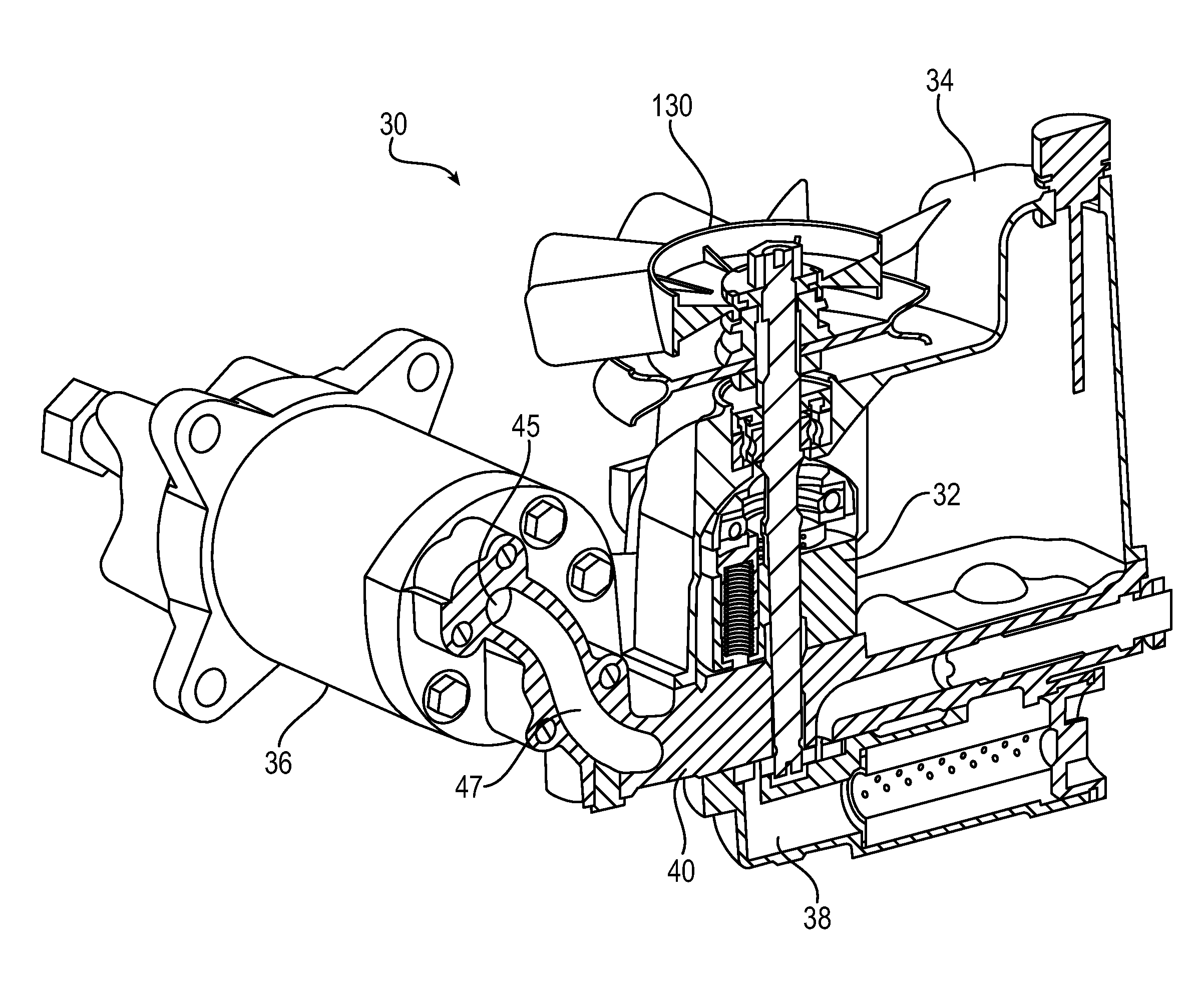
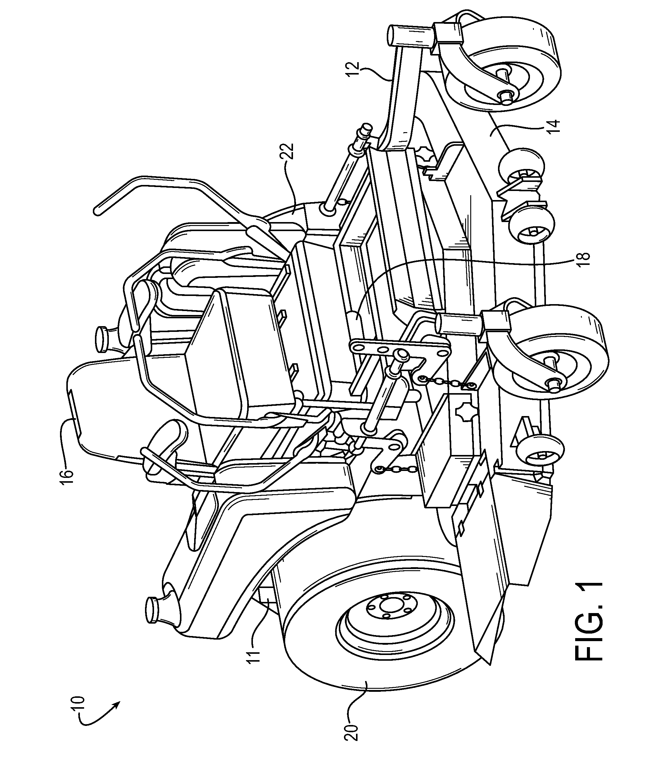
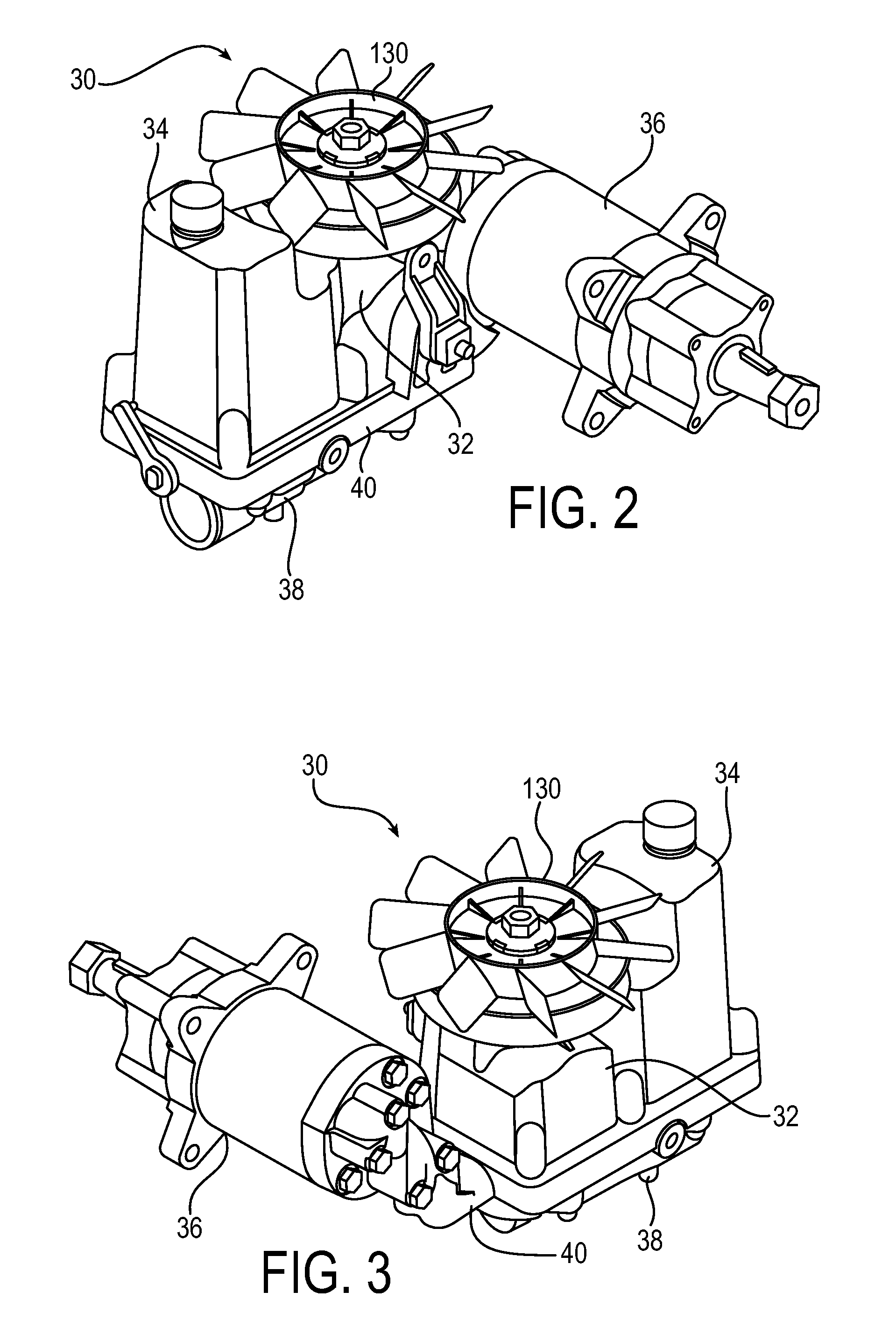
[0023]FIG. 1 is a drawing depicting a perspective view of an exemplary zero-turn-radius mower 10 employing a hydrostatic transmission in accordance with embodiments of the present invention. The mower 10 may include a frame 12, a mower deck 14 supported by the frame 12 for mowing grass, an operator seat 16, and a plurality of controls 18 for operating the mower 10. A rear mounted engine 11 as is known in the art, also referred to as a prime mover, is mounted to the frame 12 behind the seat 16 and provides power to left and right hydrostatic transmissions (the hydrostatic transmissions are not shown in FIG. 1) also mounted to the frame 12. The hydrostatic transmissions can be controlled by an operator to independently drive respective rear whee...


PUM


Abstract

A hydrostatic transmission includes a hydraulic pump, a top housing that houses the hydraulic pump, and a hydraulic motor. An endblock sub-assembly has a pump running face for interfacing with the hydraulic pump, and a motor connection portion for interfacing with a hydraulic motor. The enblock sub-assembly forms a porting manifold for communicating hydraulic fluid from the hydraulic pump to the hydraulic motor. The hydraulic motor includes an internal rotor set, and the hydraulic motor is secured to the endblock sub-assembly in a manner that permits rotation of the rotor set. The top housing is fixed to the endblock sub-assembly such that the housing and endblock sub-assembly form a reservoir for the hydraulic fluid. The motor connection portion of the endblock sub-assembly supports the hydraulic motor externally to the top housing. The hydrostatic transmission is suitable for incorporation into various light vehicle categories, including zero-turn radius vehicles.

Description

RELATED APPLICATIONS[0001]This application claims the benefit of U.S. Provisional Application No. 61 / 835,777 filed Jun. 17, 2013, which is incorporated herein by reference.FIELD OF INVENTION[0002]The present invention relates generally to transmissions, and more particularly to hydrostatic transmissions for use in light vehicles, such as turf mowing machines and zero-turn radius vehicles.BACKGROUND[0003]A prime mover, such as an internal combustion engine or the like, can be connected to a hydrostatic transmission to drive a wheel in a light vehicle. A hydrostatic transmission is particularly suitable to provide traction drive for light vehicles such as turf machines, lawn tractors, ride-on lawn mowers, and like devices. A hydrostatic transmission may be connected to a variety of gearboxes and transaxles, so the same components can be utilized on a wide variety of light vehicle models. A simple usage of hydrostatic transmissions is on zero-turn radius vehicles, including zero-turn r...

Claims


Application Information

Patent Timeline
Patent Type & Authority Patents(United States)
IPC IPC(8): F04B23/02F16H39/04F04B17/06F03C1/26
CPCF16H39/04F03C1/26F04B17/06
Inventor RICHARDSON, JASON SCOTHYNES, RICHARD C.CROSBY, MICHAEL
Owner PARKER INTANGIBLES LLC
Why Eureka
Try Eureka