Interactive simulation and solver for mechanical, fluid, and electro-mechanical systems

a technology applied in the field of interactivity simulation and solver for mechanical, fluid, and electromechanical systems, can solve the problem that 3 rarely yield a valid simulation

Active Publication Date: 2015-10-06
HEXAGON MFG INTELLIGENCE INC
View PDF19 Cites 6 Cited by
  • Summary
  • Abstract
  • Description
  • Claims
  • Application Information

AI Technical Summary

Benefits of technology

[0003]In one configuration a computer readable media may store instructions that instruct a microprocessor to create and execute a work environment for allowing a user to develop computer-aided simulations. The computer readable media may store several modules such as: a model builder for generating a simulation model and creating model objects, solver for creating solver objects, checking model validity and executing solver methods, including but not limited to solving equations, fragment collector for obtaining fragments (fragments contain one or more model objects.) of the model from the model builder and data validator for determining whether a model fragment contains sufficient data to enable fragment solution. In most embodiments, a determination as to whether the model builder and solver can use a common data representation is made at design time. If a common data representation cannot be generated, the data validator may instruct a solver object generator to form a solver object using the model fragments, and instruct a data coupler to continuously and automatically synchronize data stored in the model object and the solver object. The solver may solve a subset of the model created from the fragment

Problems solved by technology

In practice, steps 1 thru 3 rarely yield a valid simulation at the first attempt and users frequently discover modeling

Method used


Image

  • Interactive simulation and solver for mechanical, fluid, and electro-mechanical systems
  • Interactive simulation and solver for mechanical, fluid, and electro-mechanical systems
  • Interactive simulation and solver for mechanical, fluid, and electro-mechanical systems

Examples


example 1

Interactive Mesh Quality Calculations

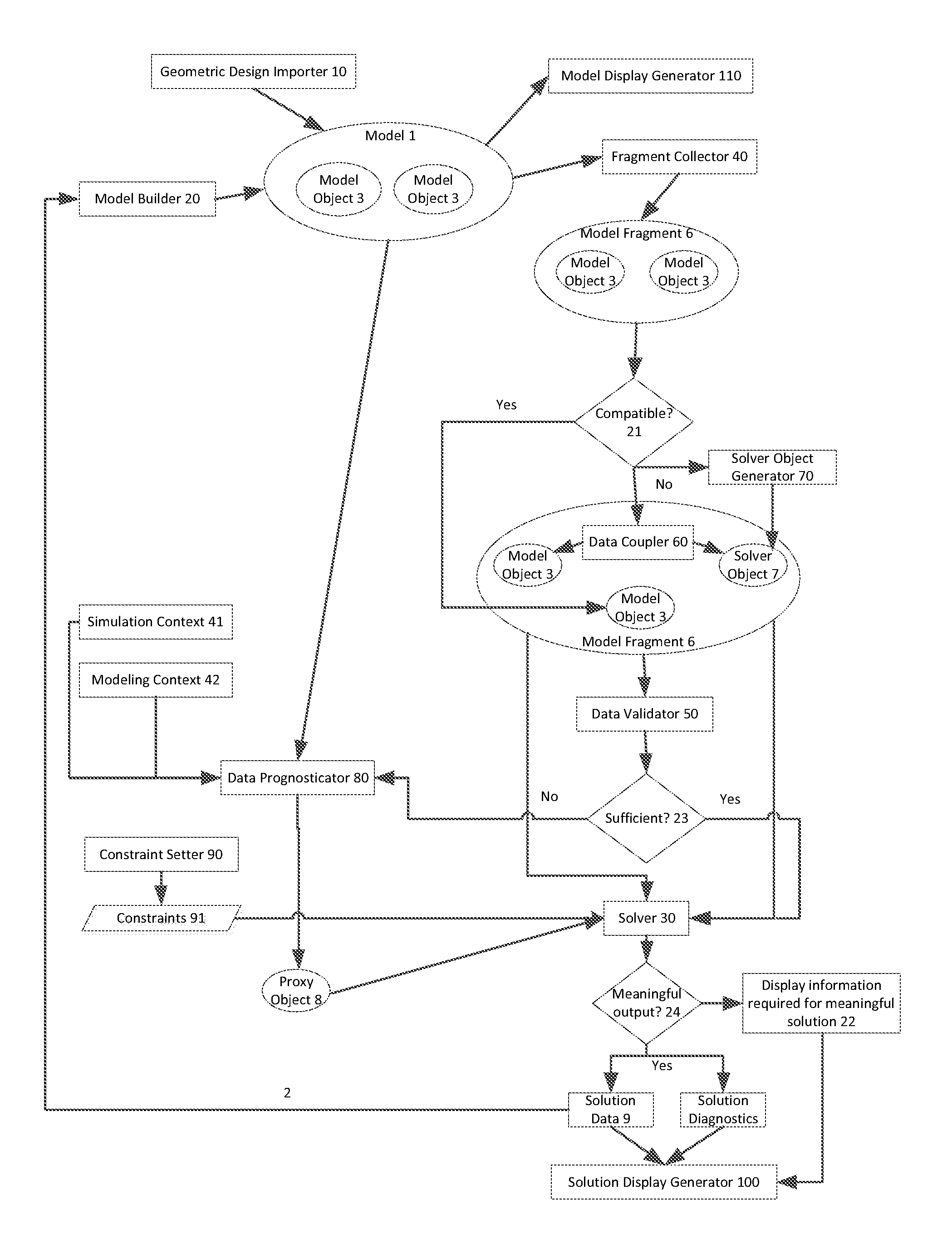
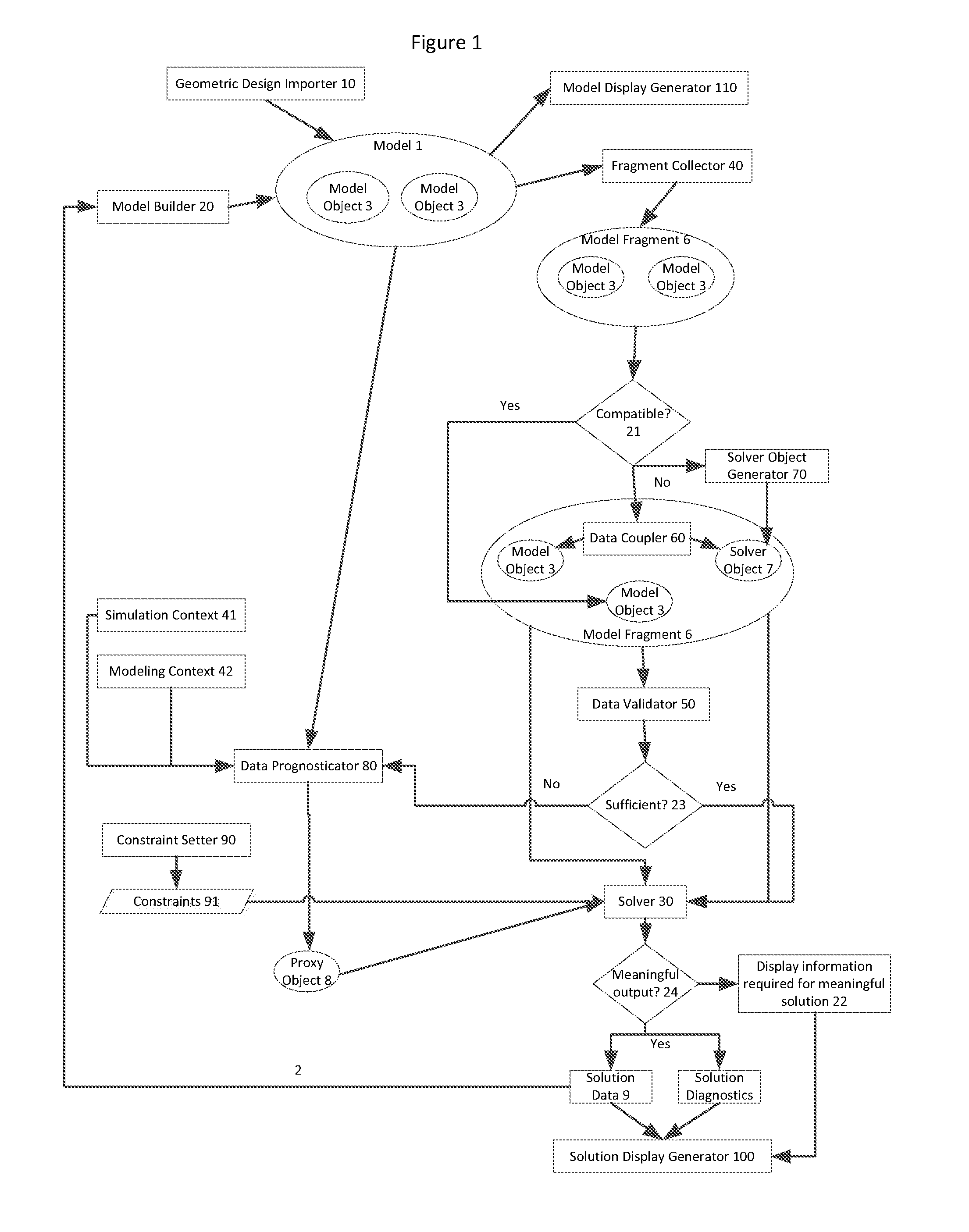
[0034]1. Object pattern: an automatically generated mesh. A mesh region is a collection of nodes and elements that are generated using a meshing algorithm. The meshing algorithm is implemented within the mesh generation service. The algorithm is the set of rules, the service is the executable code that implements these rules and transforms the input (geometry, another mesh, etc.) into a mesh.[0035]2. Trigger: Successful completion of a method of the mesh generation service (or mesh generator). This is the method that actually generates the mesh.[0036]3. Solver methods: Those solver methods that calculate the quality metrics for the elements in the mesh. Mesh quality metrics include measurements of the individual element shapes such as taper, skew, Jacobian, warpage etc.[0037]4. Output destination: The element quality data will be returned to the mesh quality container associated with the input mesh.[0038]5. Optional follow on method: Select an in...

example 2

Spot Weld Calculation

[0042]1. Object pattern: A single spot weld object or a pattern / grouping of spot weld objects. A spot weld generator may create the spot weld.[0043]2. Trigger: Successful completion of an interactive method that creates individual spot welds or patterns of multiple spot welds (like a line of spot welds with a given spacing).[0044]3. Solver methods: Solver methods that calculate connectivity of the spot weld to nodes and elements in the Parts that the spot weld joins together. This calculation may create additional modeling objects and constraints usable by the solver to calculate the response of the solver.[0045]4. Output destination: The new modeling objects and diagnostic data will be returned to a container and associated with the original spot weld modeling objects.[0046]5. Option follow on method: Select an interactive method that will cause the previously generated solver objects to be displayed on a graphics display alongside the original spot weld object...

example 3

Computational Part Generation

[0050]1. Object pattern: A Part object containing one or more mesh objects.[0051]2. Trigger: Completion of the generation of a mesh object within a Part object.[0052]3. Solver methods: Solver methods that create a reduced computation part representation from a full fidelity FE Part representation.[0053]Note that there are multiple ways to generate a computational part from a full fidelity part. The choice of computational part generation for any given model will be determined from the simulation and modeling contexts that are current within the session.[0054]Note that the methods required to create a computational part from a full fidelity part require more information than just the mesh definitions referenced in this example. These methods will use all data that is required and available within the model definition and will provide default values for any missing data. The default data values will be provided from the simulation or modeling context defau...


PUM


Abstract

The model builder may generate a model object, and initiate the solver to determine whether the model object has constraints that effect the model object. The solver can generate solution data these constraints. The solver may pass any solution data it obtains to the solution display generator, so that the user can view the solution data while the user is building the model with the model builder.

Description

BACKGROUND[0001]Techniques for rendering models often involves five basic steps: 1) creation of a finite element model, typically, but not always from geometry / design information imported from CAD systems; 2) enhancement of the finite element model with material, property, load and constraint attributes; 3) transformation of the attributed model into a formatted file suitable for consumption by a finite element solver; 4) transformation of the information contained within the formatted solver files into a set of equations and subsequent solution of these equations by the finite element solver; and 5) post-processing of the results from the solution of the equations. In practice, steps 1 thru 3 rarely yield a valid simulation at the first attempt and users frequently discover modeling deficiencies or errors after completion of steps 4 and 5 that have to be corrected by partially repeating steps 1 thru 3. This cycle of build, solve, review, fix is generally executed numerous times bef...

Claims


Application Information

Patent Timeline
IPC IPC(8): G06F17/50
CPCG06F17/50G06F17/5009G06F17/5086G06F2111/04G06F30/20G06F30/17G06F30/00
Inventor BRENNAN, DOUGLASNEILL, DOUGLAS JAMESHUNT, HERBERT DENNIS
Owner HEXAGON MFG INTELLIGENCE INC
Why Eureka
Try Eureka