Eureka AIR delivers breakthrough ideas for toughest innovation challenges, trusted by R&D personnel around the world.

Fuel cell

a fuel cell and stack technology, applied in the field of fuel cells and stacks, can solve the problems of not contributing to electricity generation by the humidifier for reaction gases, requiring an installation space, etc., and achieve the effects of high output density, uniform water distribution, and high mea durability

Active Publication Date: 2015-10-06
PANASONIC INTELLECTUAL PROPERTY MANAGEMENT CO LTD
View PDF14 Cites 0 Cited by
  • Summary
  • Abstract
  • Description
  • Claims
  • Application Information

AI Technical Summary

Benefits of technology

[0042]A fuel cell according to the present invention can circulate water within the cell even when less- or non-humidified reaction gases are supplied, thus allowing a sufficient amount of water to be retained in the fuel cell and achieving a uniform water distribution even when such reaction gases are supplied. Thus, the fuel cell offers high MEA durability and high output density.

Problems solved by technology

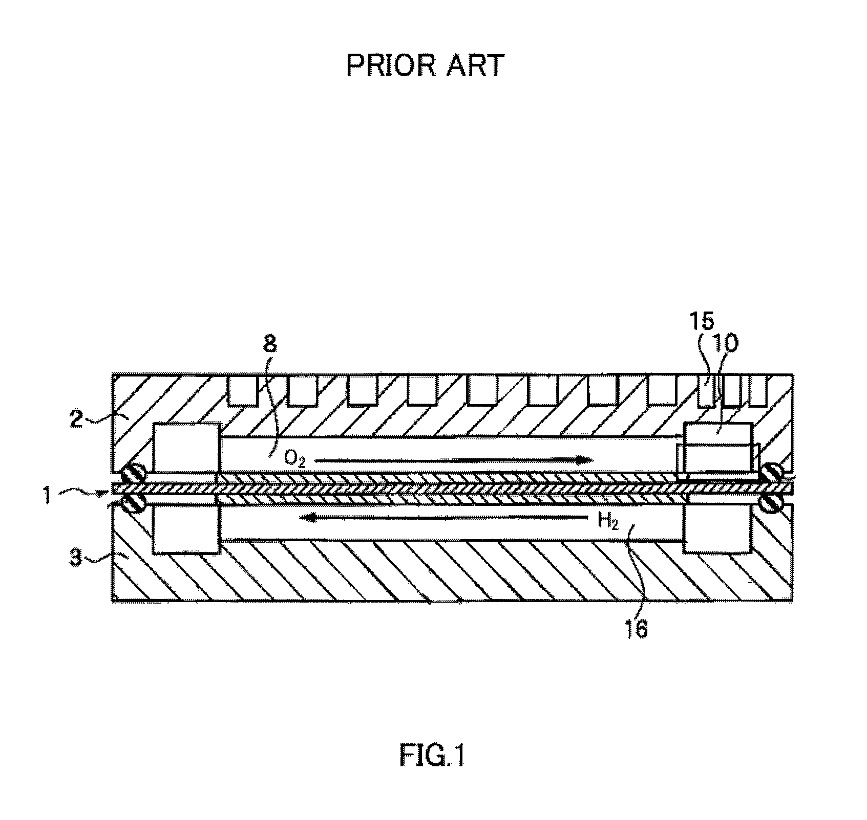
However, a humidifier for reaction gases does not contribute to electricity generation.
Moreover, it requires an installation space.

Method used


Image

  • Fuel cell
  • Fuel cell
  • Fuel cell

Examples


Embodiment Construction

[0053]A fuel cell according to the present invention includes an MEA and a pair of separators A and B between which the MEA is held. In the fuel cell, less- or non-humidified reaction gases are supplied.

[0054](1) Membrane Electrode Assembly (MEA)

[0055]The MEA includes a polymer electrolyte membrane and a pair of catalyst electrodes (fuel electrode and air electrode) between which the polymer electrolyte membrane is held. The air electrode preferably includes an air electrode catalyst layer which contacts the polymer electrode membrane, and an air electrode gas diffusion layer stacked on the air electrode catalyst layer. Similarly, the fuel cell preferably includes a fuel electrode catalyst layer which contacts the polymer electrolyte membrane, and a fuel electrode gas diffusion layer stacked on the fuel electrode catalyst layer.

[0056]The polymer electrolyte membrane is a polymer membrane which selectively transports protons in a humidified state. Materials for the polymer electrode ...


PUM

PropertyMeasurementUnit
temperatureaaaaaaaaaa

Abstract

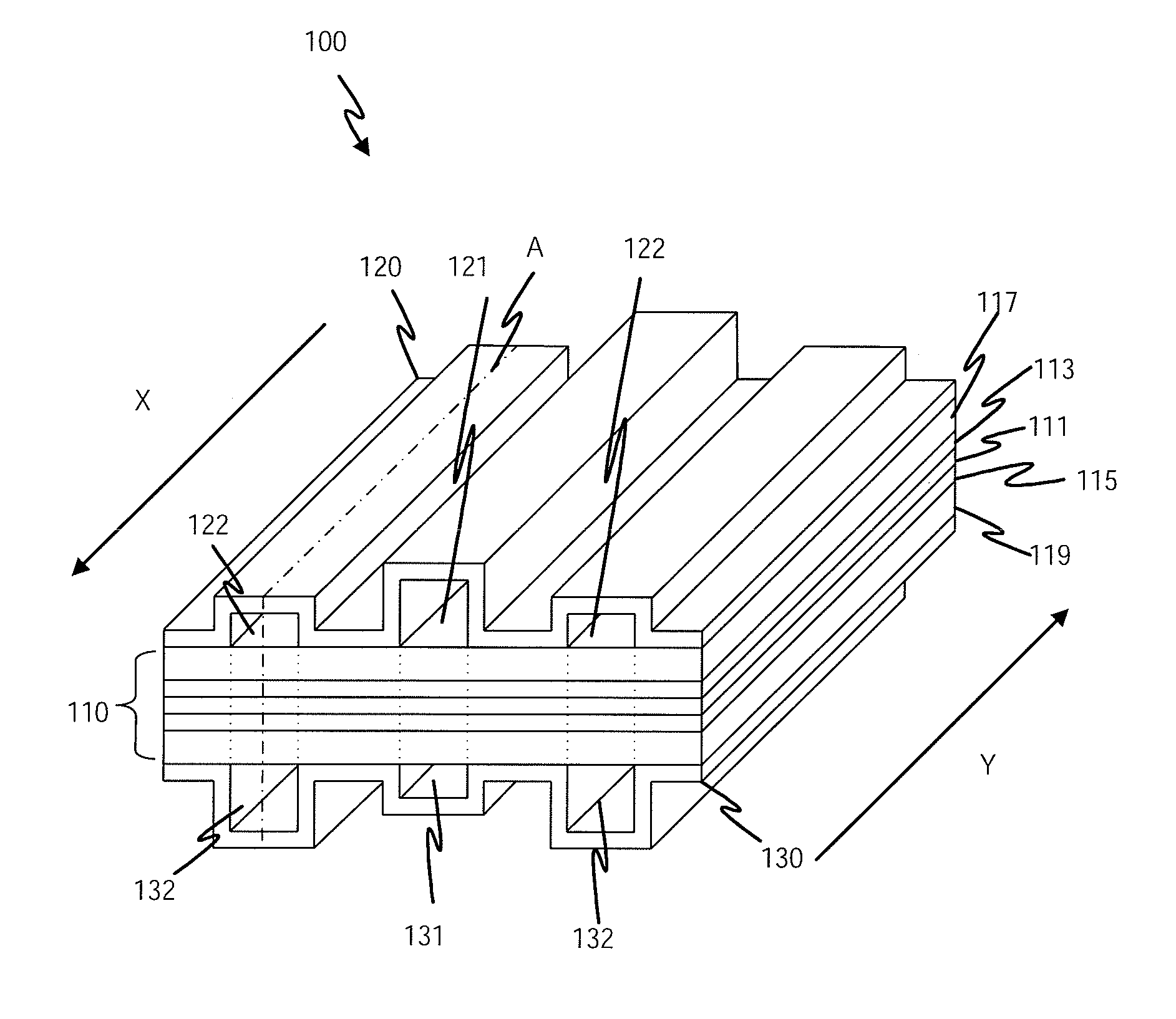
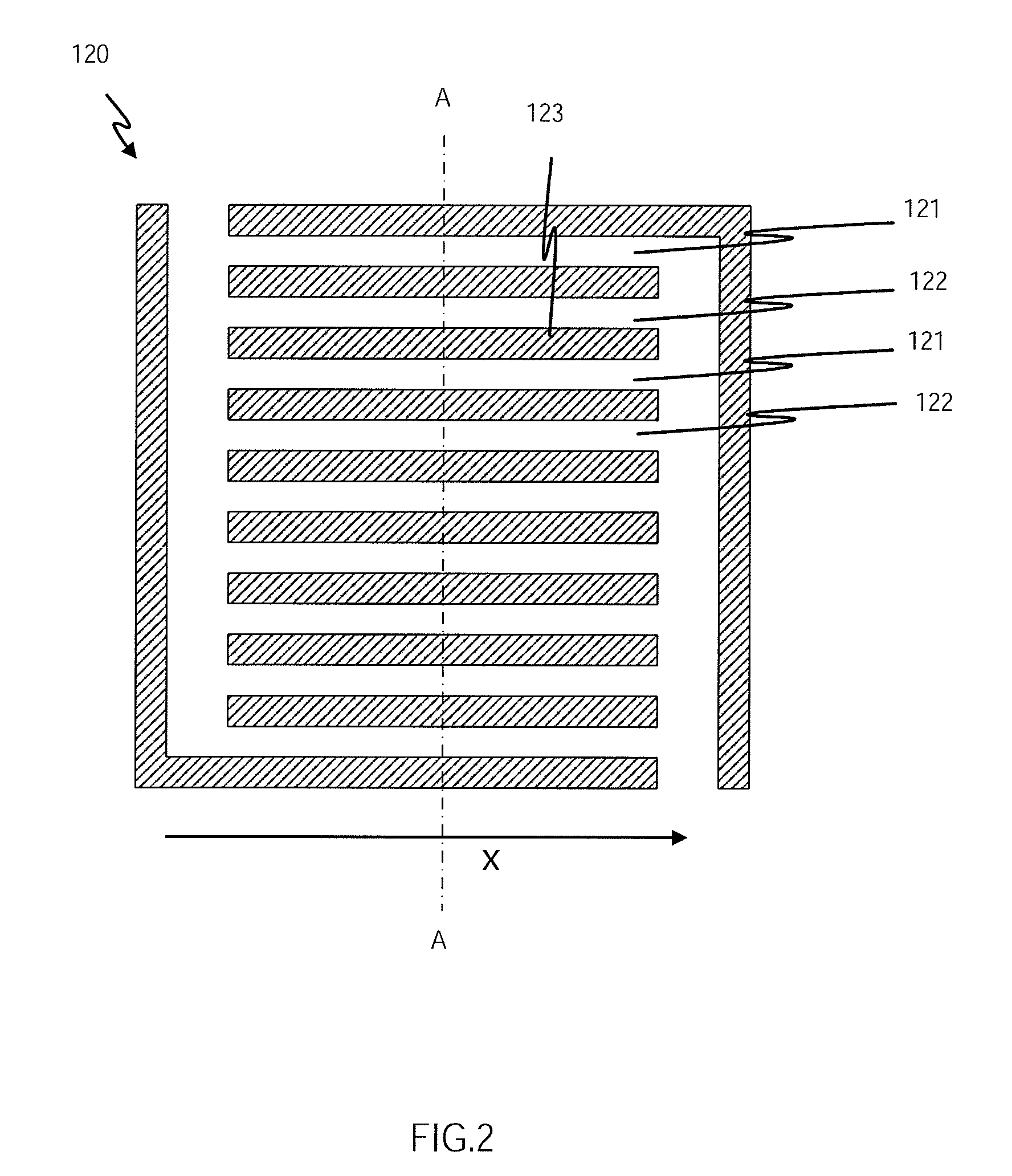
A fuel cell includes: a membrane electrolyte assembly which includes a polymer electrolyte membrane and a pair of catalyst electrodes between which the polymer electrolyte membrane is held and separators between which the membrane electrolyte assembly is held. The first separator includes first gas flow channels and second gas flow channels which are adjacent to the first gas flow channels, the first and second gas flow channels supplying an oxidizing gas or a fuel gas to the membrane electrolyte assembly. The first and second gas flow channels are parallel to each other and are alternately arranged, the first gas flow channels are larger in cross sectional area than the second gas flow channels. The second separator includes first gas flow channels parallel to the first and second gas flow channels of the first separator, and second gas flow channels which are adjacent to the first gas flow channels, the first and second gas flow channels supplying an oxidizing gas or a fuel to the membrane electrolyte assembly. The first and second gas flow channels are parallel to each other and are alternately arranged and the oxidizing gas or fuel gas supplied in the first and second gas flow channels of the first separator flows in an opposite direction to the oxidizing gas or fuel gas supplied in the first and second gas flow channels of the second separator.

Description

TECHNICAL FIELD[0001]The present invention relates to fuel cells and fuel cell stacks.BACKGROUND ART[0002]Fuel cells generally consist of a polymer electrolyte membrane which selectively transports protons and of a pair of catalyst electrodes (fuel electrode and air electrode) between which the polymer electrolyte membrane is held. Fuel cells with this configuration are capable of continuous electric energy production by using a fuel gas, a gas containing hydrogen, supplied to the fuel electrode as well as an oxidizing gas, a gas containing oxygen, supplied to the air electrode.[0003]The polymer electrolyte membrane consists of electrolyte which includes a polymer ion exchange membrane such as sulfonic group-containing fluorine resin ion exchange membrane or hydrocarbon resin ion exchange membrane. The polymer electrolyte member needs to contain a given amount of water for ion transport capability.[0004]The catalyst electrode includes a catalyst layer and a gas diffusion layer. The ...

Claims


Application Information

Patent Timeline
Patent Type & Authority Patents(United States)
IPC IPC(8): H01M8/02H01M8/04H01M8/10
CPCH01M8/026H01M8/0254H01M8/0263H01M8/0265H01M8/04291H01M2008/1095Y02E60/50
Inventor NAKAGAWA, TAKASHIMATSUMOTO, TOSHIHIROTAKEGUCHI, SHINSUKEYOSHIMOTO, MIYUKI
Owner PANASONIC INTELLECTUAL PROPERTY MANAGEMENT CO LTD
Why Eureka
Eureka Blog
Learn More