Electric motor with add-on unit, as well as a method for connecting an electric motor and an add-on unit

a technology of electric motors and add-on units, which is applied in the direction of shrinkage connections, dynamo-electric machines, electrical apparatus, etc., can solve the problems of radial deformation of connected components, high assembly costs, and high assembly costs, and achieve economic and simple assembly.

Active Publication Date: 2015-10-27
MAXON MOTOR AG
View PDF12 Cites 1 Cited by
  • Summary
  • Abstract
  • Description
  • Claims
  • Application Information

AI Technical Summary

Benefits of technology

The present invention has developed an alternative connection system for an electric motor and add-on unit. This connection system is simple and cost-effective, while still providing stable cohesion between the motor and add-on unit. The connection system can be easily assembled regardless of the size of the motor and add-on unit. Additionally, the system can be used with small and micro motors that are often required for miniaturization. The connection system involves a shrink ring that is thermally shrunk onto the motor and add-on unit, enclosing the joint area and eliminating the need for special processing or connection flanges. Overall, the invention provides an efficient, economical, and reliable connection solution for various motor and add-on unit assembly applications.

Problems solved by technology

These types of connections are either expensive or lead to radial deformations of the connected components.
The assembly proves to be extremely complex and is additionally very expensive particularly when the electric motor and add-on unit are screwed together.
This is accounted for by the fact that the bore holes in the two flanges must be made with extreme precision and the screws that are used, as additional components, make the final product more expensive.
Heating by means of induction is not suitable, however, for shrink rings made of aluminium.

Method used


Image

  • Electric motor with add-on unit, as well as a method for connecting an electric motor and an add-on unit
  • Electric motor with add-on unit, as well as a method for connecting an electric motor and an add-on unit
  • Electric motor with add-on unit, as well as a method for connecting an electric motor and an add-on unit

Examples


Embodiment Construction

[0035]In the following explanations, the same parts are indicated with the same reference numbers.

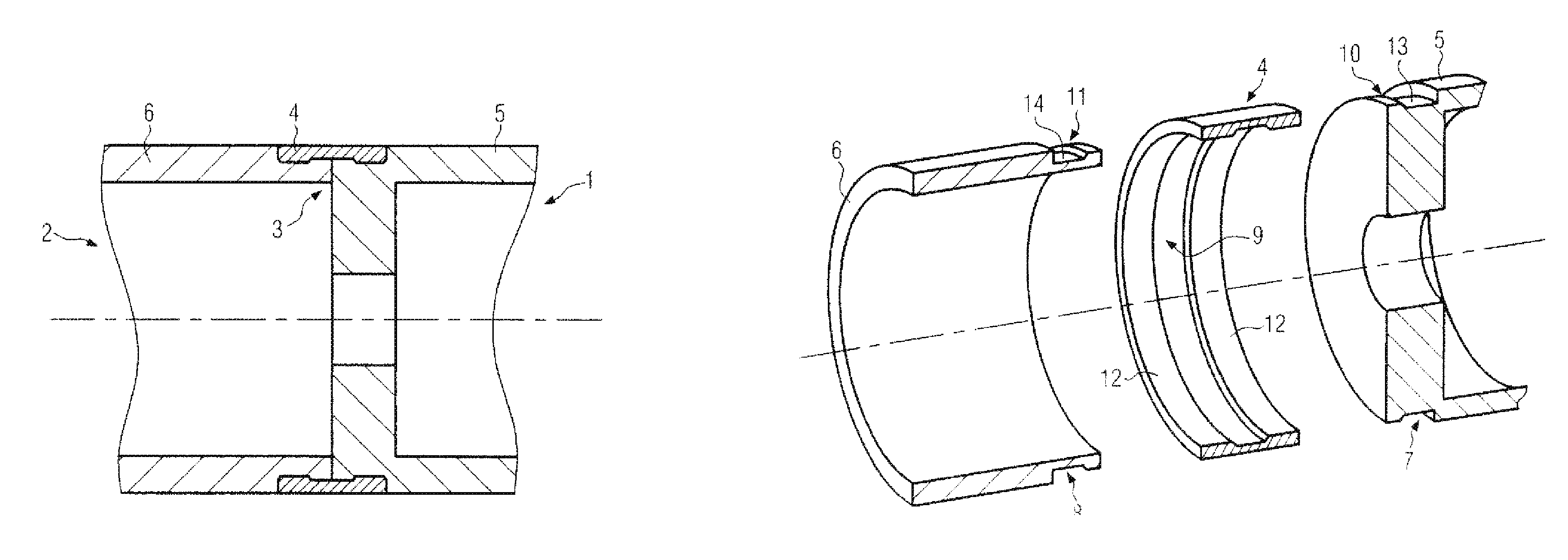
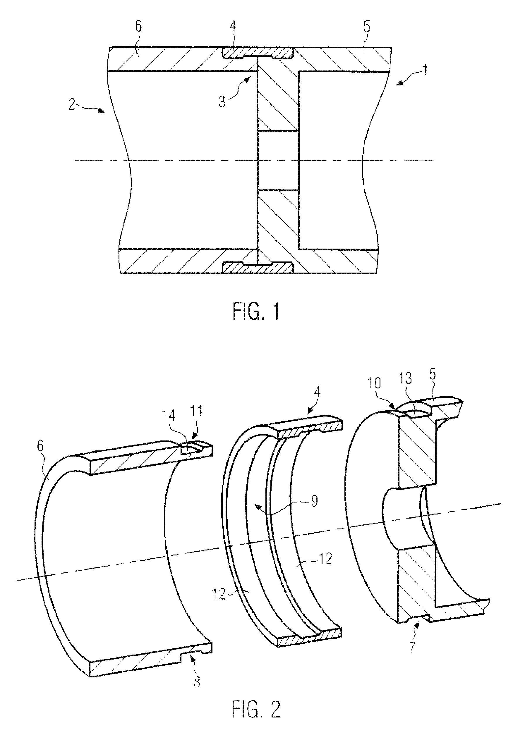
[0036]FIG. 1 shows a longitudinal section through an electric motor 1 with connected add-on unit 2 according to the invention. The add-on unit can be either a gearbox or an encoder unit or a control unit. Only the housing 5 of the electric motor 1 is shown, whereby this housing is executed in an essentially hollow cylindrical manner. Also only the housing 6 of the add-on unit 2 is depicted. The housing 6 of the add-on unit is also formed in a hollow cylindrical manner, and it has the same outer diameter as the housing 5 of the electric motor.

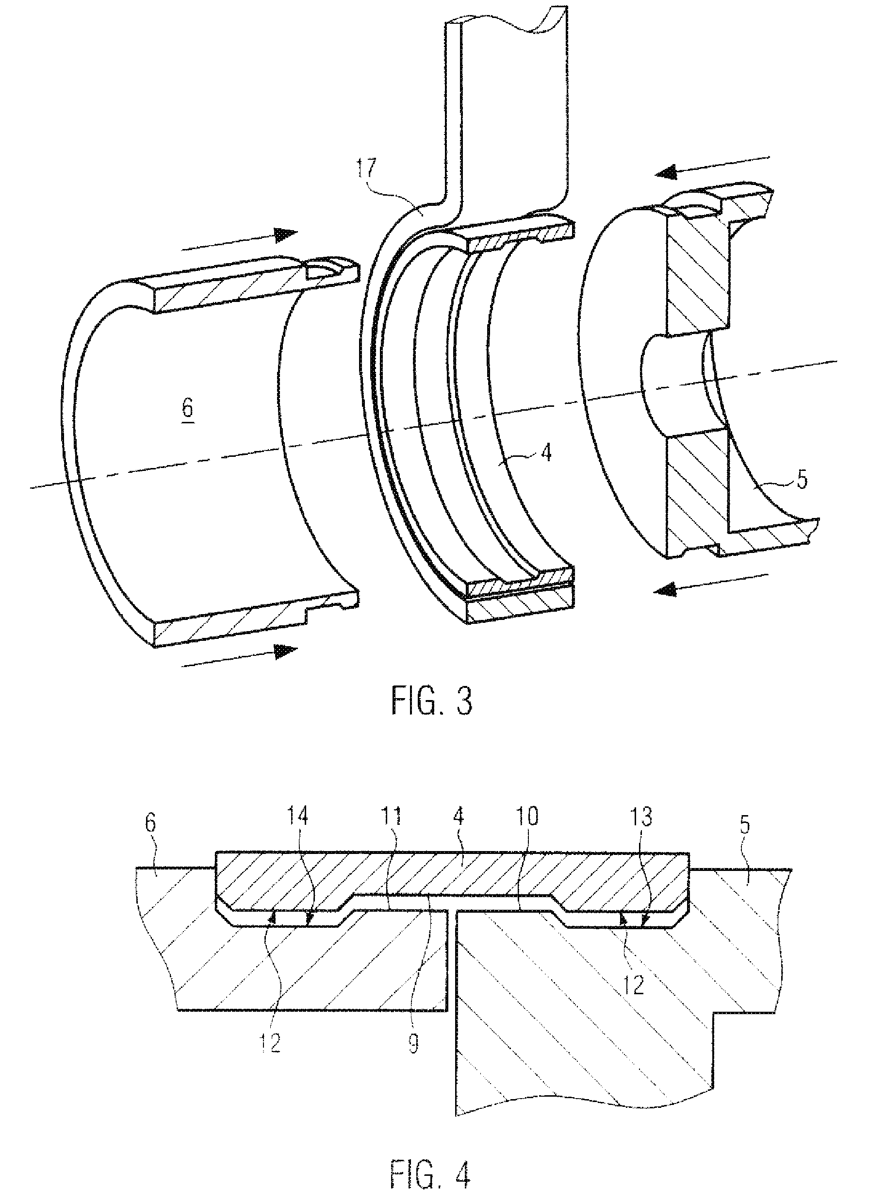
[0037]A face side of the motor housing 5 and a face side of the housing 6 of the add-on unit meet at the joint 3. The face sides can fit against each other, but they do not have to. Housing 5 and housing 6 are connected to each other by means of the shrunk on shrink ring 4. The shrink ring 4 is shrunk on to the covered areas 10 of the electric motor...


PUM

PropertyMeasurementUnit
Temperatureaaaaaaaaaa

Abstract

An electric motor with an add-on unit, such as a gearbox unit, encoder unit or controller unit, and disclosed whereby the electric motor and add-on unit can be firmly connected to each other. For a firm connection, a shrink ring is thermally shrunk on to the electric motor and add-on unit in the area of the joint so that the shrink ring covers the joint. A method is also disclosed for producing the connection, wherein a temperature difference is first created between the shrink ring on the one hand and the electric motor as well as add-on unit on the other hand, whereby furthermore the temperature of the shrink ring is greater than the temperature of the electric motor and add-on unit and whereby the components are then joined together and held so that the shrink ring shrinks on to the electric motor and add-on unit.

Description

RELATED APPLICATION[0001]This application claims priority under 35 U.S.C. §119 to European Patent Application No. EP 11003502.9 filed in Europe on Apr. 28, 2011, the entire content of which is hereby incorporated by reference in its entirety.FIELD[0002]The present invention relates to an electric motor with an add-on unit and to a method for connecting an electric motor and an add-on unit.BACKGROUND INFORMATION[0003]According to today's requirements, electric motors are often used with an add-on unit that is firmly connected to the electric motor. For example, in many cases it is necessary to equip the electric motor with a firmly connected gearbox unit in order to make it possible to provide the required torque while keeping a compact design. Often additional add-on units, such as encoder units or controller units, are also firmly connected to the electric motor. Together, the electric motor and the add-on unit form an assembly that itself represents a unit and that is manufactured...

Claims


Application Information

Patent Timeline
IPC IPC(8): H02K7/00H02K5/00F16B4/00
CPCH02K5/00F16B4/006Y10T29/49865
Inventor SUZUKI, TSUNEONEUMANN, JOACHIMSTRICKER, WOLFGANGFREY, DOMINIK
Owner MAXON MOTOR AG
Why Eureka
Try Eureka