Valve for the control of fluids

a valve and fluid technology, applied in the direction of valve housing, valve operating means/release devices, machines/engines, etc., can solve the problems of fuel leakage, fuel leakage at the valve, sweat leakage, etc., and achieve the effect of reducing the strength of the component, simple sealing, and being furnished especially cheaply

Inactive Publication Date: 2005-08-16
ROBERT BOSCH GMBH
View PDF3 Cites 3 Cited by
  • Summary
  • Abstract
  • Description
  • Claims
  • Application Information

AI Technical Summary

Benefits of technology

[0009]Preferably, the sealing element is embodied as a plastic ring or as a shrink-fit hose. The shrink-fit hose is preferably made from plastic, such as PTFE, and is placed over the male thread on the component. When the lock nut is mounted on the component that has the male thread, the shrink-fit hose then presses against the thread courses such that secure sealing is obtained.
[0010]To enable simple positioning of the plastic ring, a recess for receiving the plastic ring is preferably embodied on the lock nut. Especially preferably, this recess is provided on the upper end of the lock nut.
[0011]To enable secure positional fixation of the plastic ring on the lock nut, the plastic ring preferably has at least one protruding region, which engages a correspondingly formed additional recess on the lock nut. To that end, one or more bores or one or more grooves can be provided on the lock nut. An inward-oriented flanged-over portion can also be provided on the outermost end region of the lock nut.
[0013]In order to absorb any sweat leakage that might occur between the individual components of the valve, a groove is preferably provided between two components, by way of which groove the leakage can be carried away into a low-pressure region of the valve.
[0014]The present invention is used particularly in fuel injection valves for reservoir-type injection systems, such as common rail injection systems. As a result of the sealing between the lock nut and the components of the valve, a low-pressure region of the valve is sealed off from the outside. The sealing elements of the invention are designed such that once the valve has been disassembled, easy reassembly together with the sealing element is possible.

Problems solved by technology

By using the individual components in combination with the high pressure in reservoir-type injection systems, however, sealing problems arise that can cause leakage of fuel at the valve.
Because of an asymmetrical arrangement of bores in the components, particularly between an actuator bore and a high-pressure bore, different rigidities in the circumferential direction result, so that so-called sweating leaks can occur.
In addition, there are typically uneven places and roughness on the flat sealing faces of the individual components, which can again cause leaks.
Furthermore, because of the heavy load via the high pressures per unit of surface area, deformations can occur at the sealing planes between the individual components, which can also cause a leakage of fuel.
In this known version, however, particularly when an O-ring is used, assembly problems can arise, since during the assembly the O-ring can become twisted, as a result of which the seal can no longer be reliably assured.
Moreover, because of the recess formed in the retaining body for receiving the sealing element, additional notch points are created in the valve, at which cracking can develop in the component.

Method used


Image

  • Valve for the control of fluids
  • Valve for the control of fluids
  • Valve for the control of fluids

Examples


Embodiment Construction

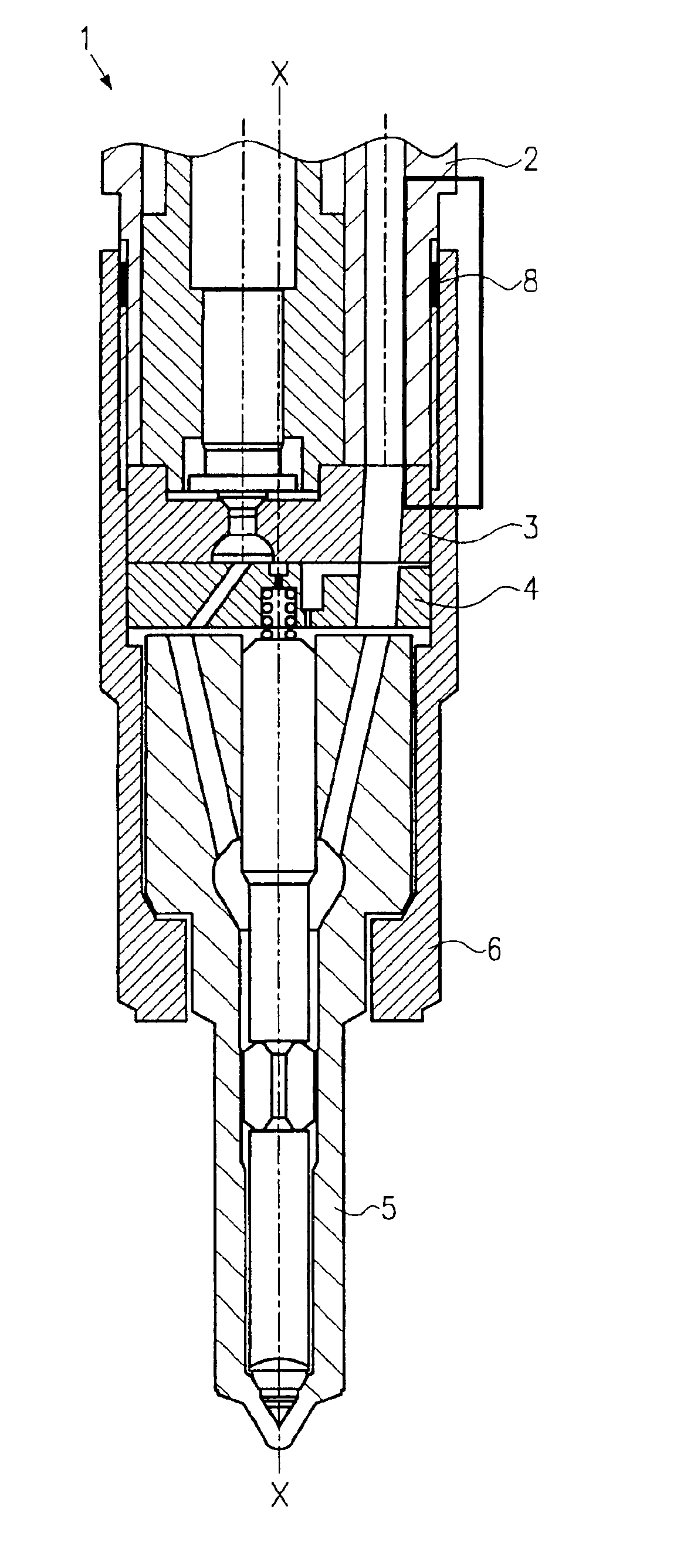
[0024]Below, a valve 1 with a sealing element in accordance with a first exemplary embodiment of the present invention will be described in conjunction with FIGS. 1 and 2.

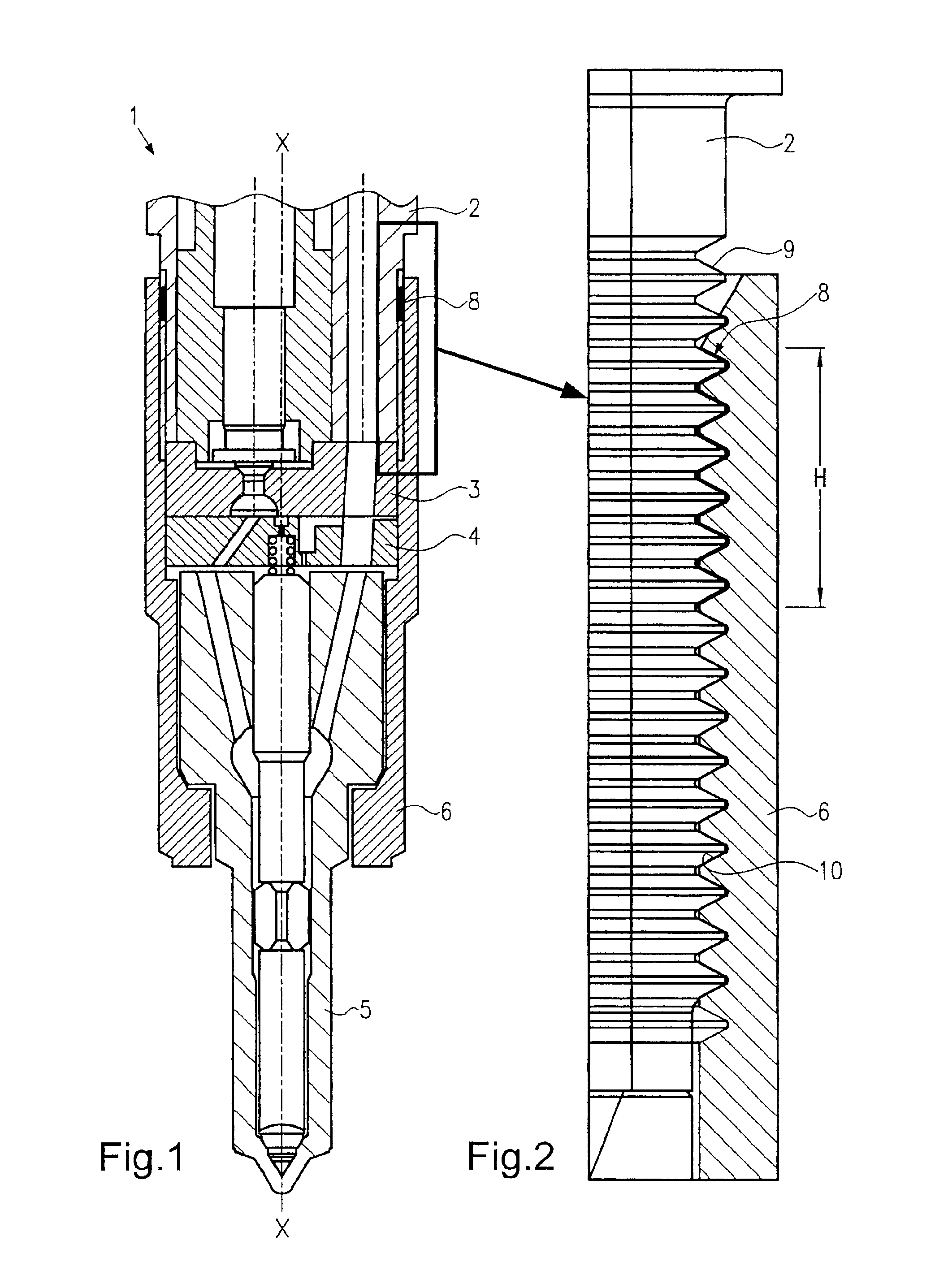
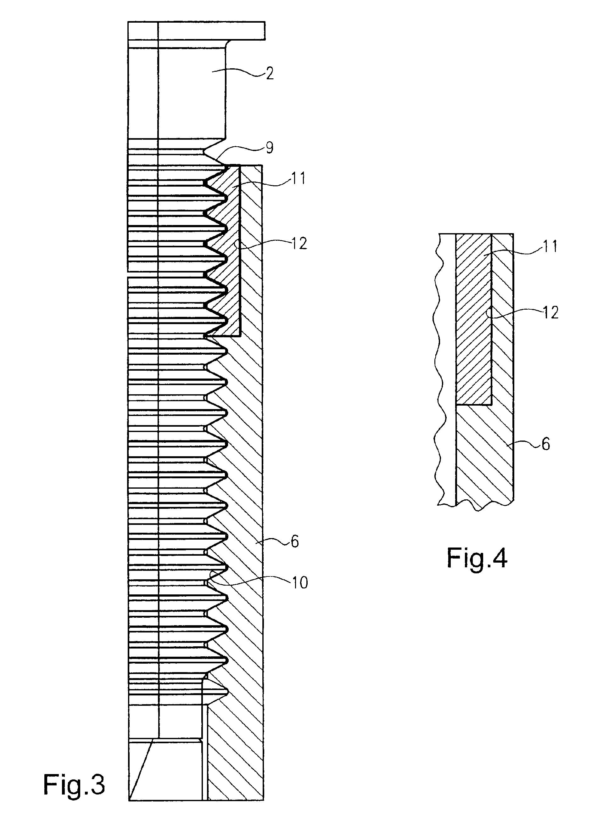
[0025]In FIG. 1, a fuel injection valve 1 is shown, which essentially comprises a plurality of components disposed in succession in the axial direction X—X of the valve. The components of the valve 1 are a retaining body 2, a valve plate 3, a throttle plate 4, and a nozzle body 5. These components of the valve are braced against one another by means of a nozzle lock nut 6. To that end, the nozzle lock nut 6, in its upper end region, has a female thread 10 (see FIG. 2), with which it is screwed onto a male thread 9 of the retaining body 2.

[0026]As shown particularly in FIG. 2, a sealing element in the form of a coating 8 is disposed between the female thread 10 of the nozzle lock nut 6 and the male thread 9 of the retaining body 2. The coating 8 can be applied either to the female thread 10 or the male thread 9 or b...


PUM


Abstract

A valve for controlling fluids, which has a plurality of components that are disposed in succession in the axial direction of the valve. On at least one of the components, a male thread is embodied in order to enter into engagement with a female thread of a lock nut. The lock nut serves to brace the components of the valve. A sealing element is disposed between the female thread of the lock nut and the male thread of the component.

Description

CROSS-REFERENCE TO RELATED APPLICATIONS[0001]This application is a 35 USC 371 application of PCT / DE 02 / 04119 filed on Nov. 7, 2002.BACKGROUND OF THE INVENTION[0002]1. Field of the Invention[0003]The present invention relates to a valve for controlling fluids and more particularly to an injection valve for injecting fuel into a combustion chamber of an internal combustion engine.[0004]2. Description of the Prior Art[0005]Injection valves for injecting fuel into a combustion chamber of an internal combustion engine are known in various embodiments. For instance, such injection valves are used in conjunction with reservoir-type injection systems, in which fuel is stored in a reservoir at high pressure in order to enable injection of the fuel at a constant pressure. Such injection valves comprise multiple components, such as a retaining body, a valve plate, a throttle plate, and a nozzle body, that are disposed in succession in the axial direction of the valve. The individual components...

Claims


Application Information

Patent Timeline
Patent Type & Authority Patents(United States)
IPC IPC(8): F02M61/00F02M61/16F02M47/02F02M63/00
CPCF02M61/16F02M61/168F02M47/027F02M63/0026F02M2200/16F02M2200/8076
Inventor KIENZLER, DIETERUHLMANN, DIETMAR
Owner ROBERT BOSCH GMBH
Why Eureka
Try Eureka