Unidirectional catheter control handle with tensioning control

a control handle and unidirectional technology, applied in the field of catheters, can solve the problems of o-rings not consistently providing sufficient friction, the operator's constant attention to the catheter, and the change or loss of the deflection of the catheter, so as to increase the frictional engagement, reduce the force applied, and increase the force applied

Active Publication Date: 2015-11-03
BIOSENSE WEBSTER (ISRAEL) LTD
View PDF29 Cites 5 Cited by
  • Summary
  • Abstract
  • Description
  • Claims
  • Application Information

AI Technical Summary

Benefits of technology

[0007]In one embodiment, the catheter includes a flexible tubing, and a control handle having a housing and a piston in a telescopic configuration, where the piston has a thumb control and the piston is longitudinally slidable relative to the housing by a user via the thumb control for deflecting the tubing. Advantageously, the control handle includes a tension adjustment assembly that provides a force member adapted for applying a force on the piston, and a knob rotationally coupled to the force member, where the knob is adapted for rotation by the user to adjust the force applied on the piston by the force member. The force includes contact, pressure and / or friction between the piston and the housing of the control handle and allows the piston to be releasably locked in a desired position relative to the housing, repositioned relative to the housing and adjustment of the ease by which the piston can be moved relative to the housing. The tension adjustment assembly may also include a guide which limits the range of motion of the knob so as to prevent damage to the piston and / or housing, or disassembly or detachment of the tension adjustment assembly.
[0009]The knob is configured for rotation in one direction to increase the force applied by the set screw on the piston and in an opposition direction to decrease the force applied by the set screw on the piston, where increasing the frictional engagement locks the piston and the housing in a desired position and decreasing the frictional engagement unlocks the piston and the housing and allows repositioning of the piston and the housing relative to each other.

Problems solved by technology

Because the patient's heart is active with blood flow and moving walls and chambers, the catheter is subjected to forces that may cause the catheter to change or lose the deflection without an operator's constant attention and manipulation.
However, the O-ring may not consistently provide sufficient friction to hold the piston and maintain the desired deflection.

Method used


Image

  • Unidirectional catheter control handle with tensioning control
  • Unidirectional catheter control handle with tensioning control
  • Unidirectional catheter control handle with tensioning control

Examples


Embodiment Construction

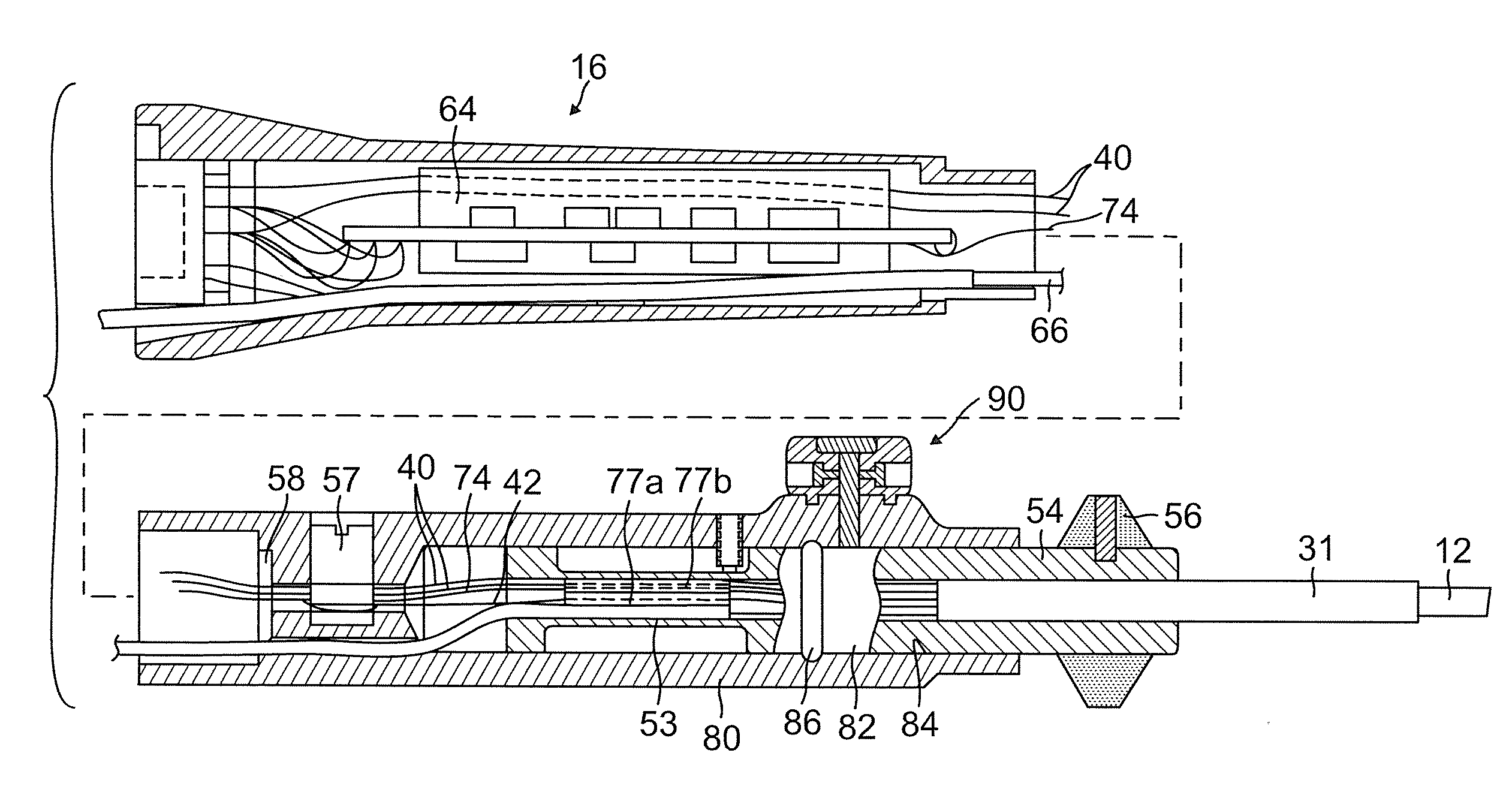
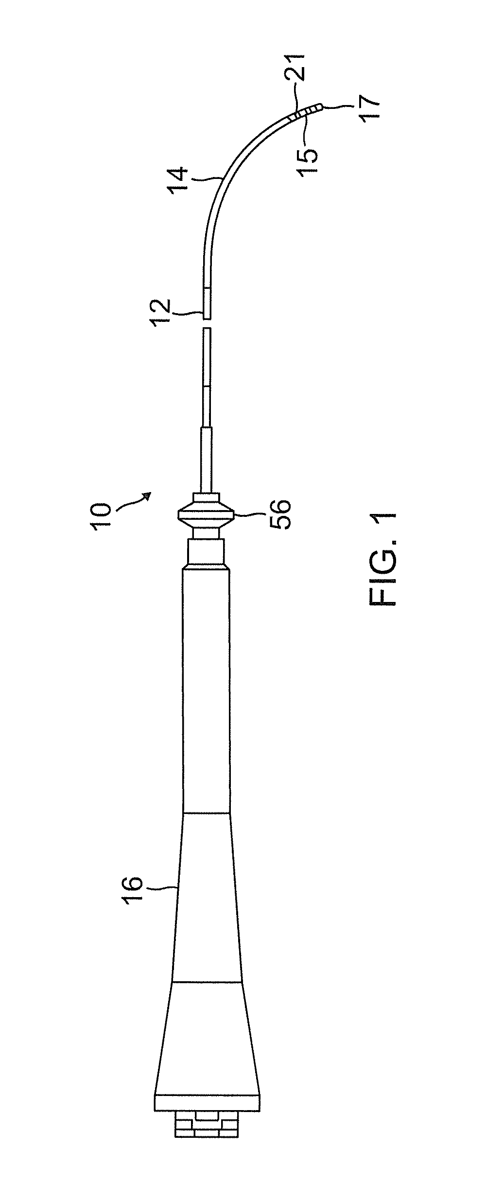
[0020]FIG. 1 illustrates an embodiment of a catheter 10 with an elongated catheter body 12, an deflectable intermediate section 14, a distal section 15 with a tip electrode 17 and an improved control handle 16 employing a piston 54 housed in a handle housing for unidirectional deflection that advantageously provides a tension adjusting mechanism 55 that allows an operator to releasably lock the piston in a particular position relative to the handle housing, and allow repositioning of the piston to a different position and adjusting of the amount of force needed to reposition the piston. As such, the control handle provides a user with an enhanced ability to accurately position the catheter within the patient's body.

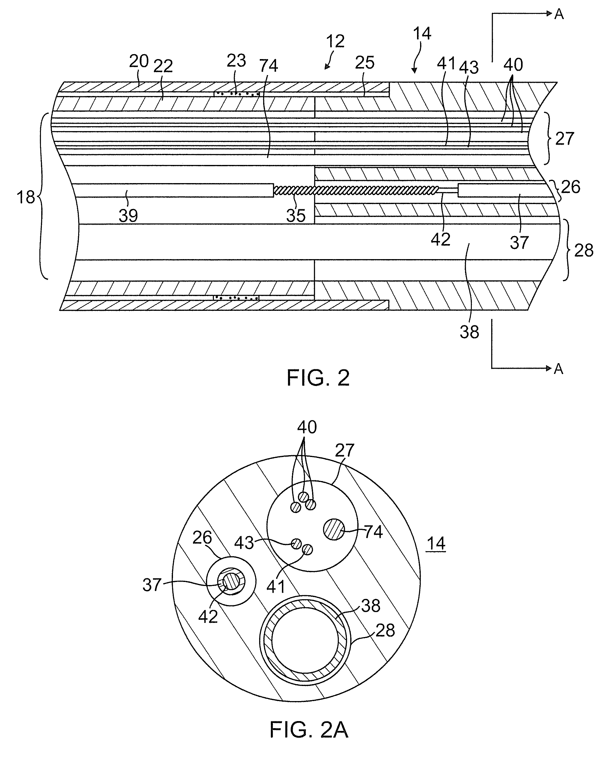
[0021]With reference to FIGS. 1 and 2, the catheter body 12 comprises an elongated tubular construction having a single, axial or central lumen 18. The catheter body 12 is flexible, i.e., bendable, but substantially non-compressible along its length. The catheter body 12 ...


PUM


Abstract

A catheter includes a tip electrode with a shell and a support member to provide a plenum chamber. The plug is formed with a U-shaped passage for a safety line to wrap around and secure the support member (with the shell affixed thereto) to the catheter. Additional passages are formed in the plug to accommodate components such as irrigation tubing, lead wire and thermocouple wire pair. A method of manufacture provides distal installation and / or anchoring of the safety line, lead wire and thermocouple wire pair in the support member prior to sealing the support member and mounting the shell.

Description

FIELD OF INVENTION[0001]The present invention relates to catheters, particular catheters with a deflectable portion and a control handle to control deflection.BACKGROUND OF INVENTION[0002]Electrode catheters have been in common use in medical practice for many years. They are used to stimulate and map electrical activity in the heart and to ablate sites of aberrant electrical activity. In use, the electrode catheter is inserted into a major vein or artery, e.g., femoral artery, and then guided into the chamber of the heart of concern. Within the heart, the ability to control the exact position and orientation of the catheter tip is critical and largely determines how useful the catheter is.[0003]A typical mapping or ablation catheter has an elongated catheter body, an intermediate deflectable section, a distal section carrying one or more electrodes, and a control handle in which the proximal end of at least one puller wire is anchored. The puller wire extends distally through the c...

Claims


Application Information

Patent Timeline
Patent Type & Authority Patents(United States)
IPC IPC(8): A61M25/01A61B18/14A61B19/00A61B18/00
CPCA61M25/0147A61B18/14A61M25/0136A61B18/1492A61B2018/00351A61B2019/5251A61B2218/002A61B2034/2051A61B34/20A61B5/6852A61B5/283A61B2017/00323A61M2210/125
Inventor GRUNEWALD, DEBBY
Owner BIOSENSE WEBSTER (ISRAEL) LTD
Why Eureka
Try Eureka