
Hopper tee with comformable arcuate closure member

a technology of arcuate and hopper tee, which is applied in the direction of pipeline expansion compensation, pipe units with cleaning apertures, packaging, etc., and can solve problems such as affecting the performance of the hopper tee, and achieve the effect of reducing the downtim

Inactive Publication Date: 2015-11-03
BULK TANK
View PDF34 Cites 2 Cited by
  • Summary
  • Abstract
  • Description
  • Claims
  • Application Information

AI Technical Summary

Benefits of technology

The fluted hopper tee increases unloading rates by up to 22%, reduces heat generation during unloading, and provides improved ground clearance, leading to faster unloading times, reduced wear, and lower fuel consumption for trucking companies.

Problems solved by technology

Reduction in product surges leads to less instances of plugged unloading lines and the resultant downtime during an unload cycle.

Method used


Image

  • Hopper tee with comformable arcuate closure member
  • Hopper tee with comformable arcuate closure member
  • Hopper tee with comformable arcuate closure member

Examples


Embodiment Construction

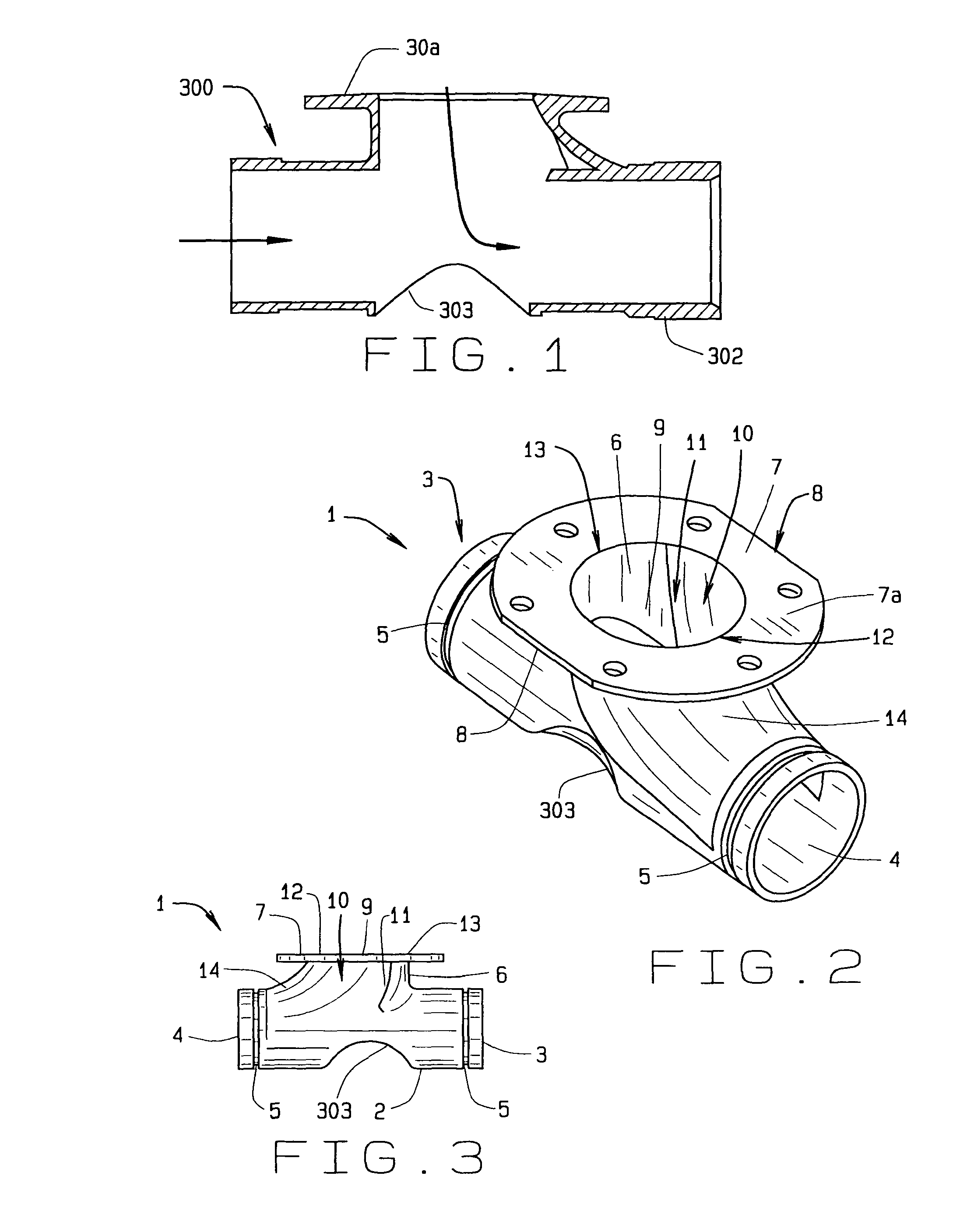
[0058]In referring to the drawings, FIG. 1 shows a drop tee, having an arcuate style of bottom, wherein the tee 300 includes a flanged vertical section 301, a horizontal or longitudinal section integrated into the structure of the tee, as noted at 302, and further incorporates that arcuate opening through its bottom, as at 303, that provides for unloading of the hopper bin or tank trailer directly through the shown attached tee 300.

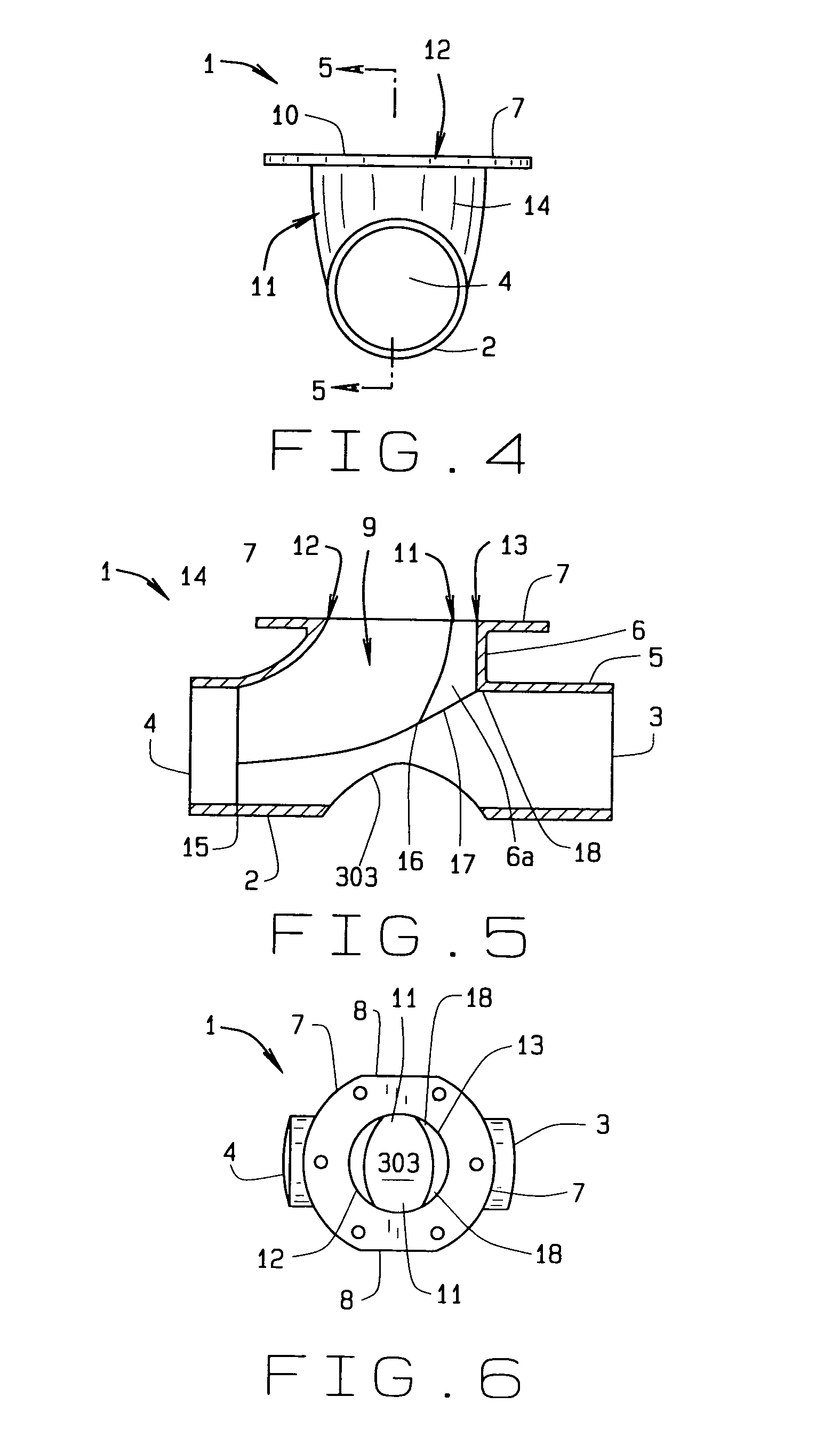
[0059]In referring to the drawings, FIG. 2 also shows the integral tee, generally known as a hopper tee, of the present invention 1 in a perspective view. The present invention has a generally transverse hollow pipe, hereinafter horizontal pipe 2, round in cross section and of a known diameter. The horizontal pipe has two opposed ends, one end being an inlet 3 that receives material sent into the hopper tee under pneumatic pressures from another source, and the opposite end being an outlet 4 that discharges material from the inlet and the materials as unl...


PUM


Abstract

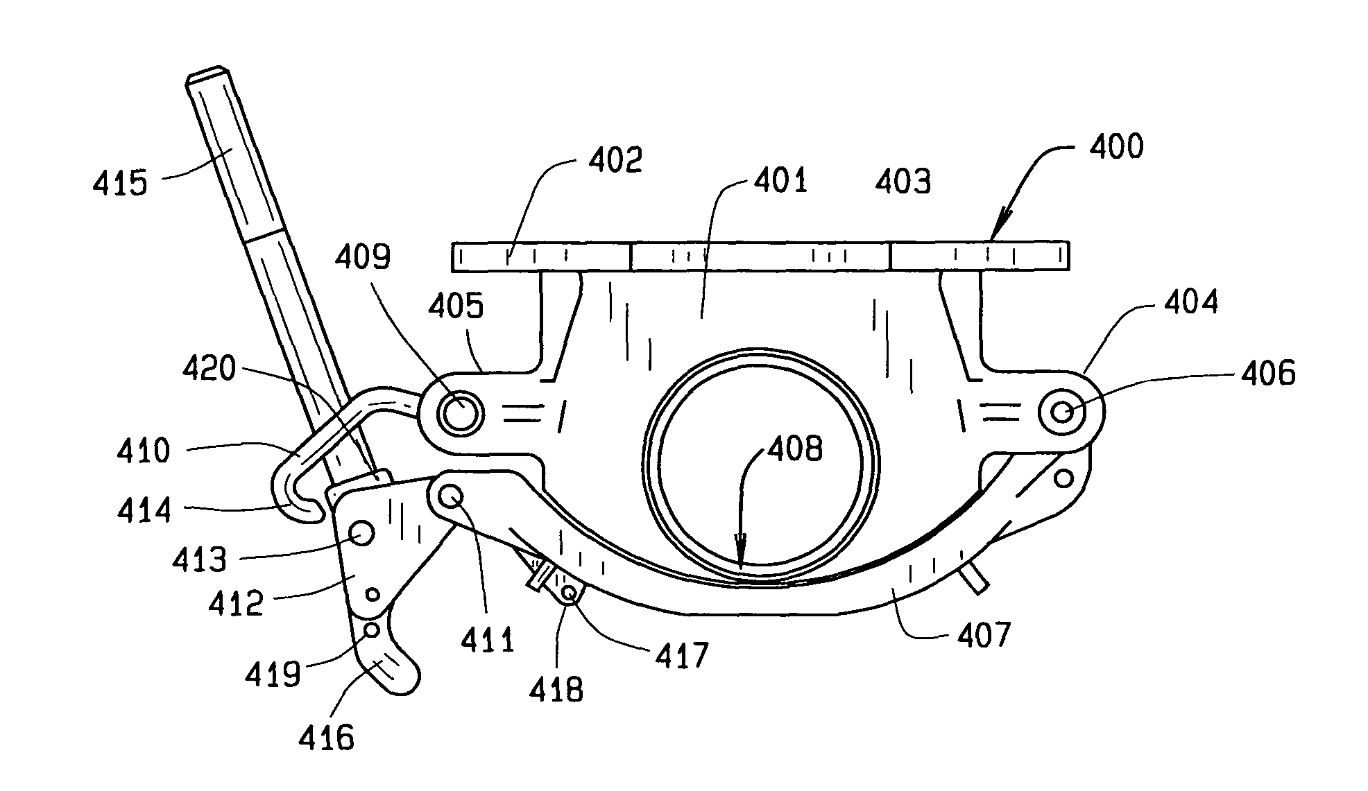
A directional hopper tee has a fluted interior vertical pipe that merges into a horizontal pipe. The horizontal pipe has an inlet that may receive bulk material, and subject to pressurized air that conveys the bulk material through the hopper tee. Bulk material may be discharged from a hopper through the vertical pipe, for conveyance for discharge from the horizontal pipe of the tee. A closure gate or door is provided through the bottom of the tee, generally in alignment with the vertical pipe, to allow for discharge or dropping of the granular material directly downwardly through and from the tee. The arcuate door is hinged on one side, and is locked by a cam lock on the opposite side, when located into closure against the bottom of the tee, but can be forced opened, through its cam mechanism, to provide for opening of the arcuate door and allow a direct downward discharge of the granular bulk material, from any hopper, and through the drop opening of the tee, as required.

Description

CROSS REFERENCE TO RELATED APPLICATION[0001]This application claims priority to the non-provisional patent application having Ser. No. 13 / 200,625, filed on Sep. 27, 2011, which claims priority to the non-provisional patent application having Ser. No. 12 / 249,672, filed on Oct. 10, 2008, now U.S. Pat. No. 8,091,925, which latter application claims priority to the provisional application having Ser. No. 61 / 030,777, having a filing date of Feb. 22, 2008, which is related to U.S. Pat. No. 6,786,362, which also claims priority to that non-provisional patent application having Ser. No. 12 / 249,672, filed on Oct. 10, 2008, now U.S. Pat. No. 8,091,925; and this application also claims priority as a continuation-in-part to the application having Ser. No. 13 / 506,244, filed on Apr. 6, 2012, which claims priority to provisional patent application having Ser. No. 61 / 517,041, filed on Apr. 12, 2011; this application is also related to Ser. No. 61 / 744,389, filed on Sep. 26, 2012; which also relates ...

Claims


Application Information

Patent Timeline
Patent Type & Authority Patents(United States)
IPC IPC(8): F16L41/00F16L41/02B65D90/62B65D88/28
CPCF16L41/021B65D88/28B65D90/623
Inventor SISK, DAVID E.
Owner BULK TANK
Learn More