
Plant container assembly and method

a plant container and container base technology, applied in the field of containers, can solve the problems of significant stability problems, circling of roots, stem girdling roots, etc., and achieve the effect of encouraging air root pruning and vast improvement of root regeneration

Active Publication Date: 2015-11-10
JENSEN LARS
View PDF52 Cites 8 Cited by
  • Summary
  • Abstract
  • Description
  • Claims
  • Application Information

AI Technical Summary

Benefits of technology

[0011]The present invention provides a bounding system for a transplantable plant for bounding a growing medium in which the transplantable plant is grown. Therefore, root regeneration is vastly improved. The bounding system includes a bounding apparatus having a sheet-like lattice framework, which is comprised of a plurality of elongated rib members, spaced apart from one another. Each elongated rib member defines an interior facing surface that is convex-shaped in a transverse cross-sectional dimension thereof. Further, each adjacent elongated rib member defines an elongated, spaced sidewall apertures therebetween, and hence a plurality of sidewall aperture that collectively define a sidewall aperture area. This sidewall aperture area comprises at least about 50% of the sidewall surface area. The bounding apparatus further includes s bottom support having a support surface area. The bottom support and the sidewall framework cooperate to define a cavity formed for receipt of the growing medium therein. The bottom support further include a sheet-like bottom framework having a plurality of spaced bottom wall apertures which promote and encourage air root pruning of the transplantable plant proximate the bottom support when vertically oriented at a location above the ground by a sufficient distance.
[0012]Accordingly, the convex interior profile of the interior facing surface of each elongated rib members (regardless of their orientation) facilitates any root growth contacting these surfaces to be deflected into and through the respective adjacent sidewall apertures. Unlike the current designs were the interior wall are relatively flat, any such root growth directly contacting such a surface will not be directed back inward toward into the container.
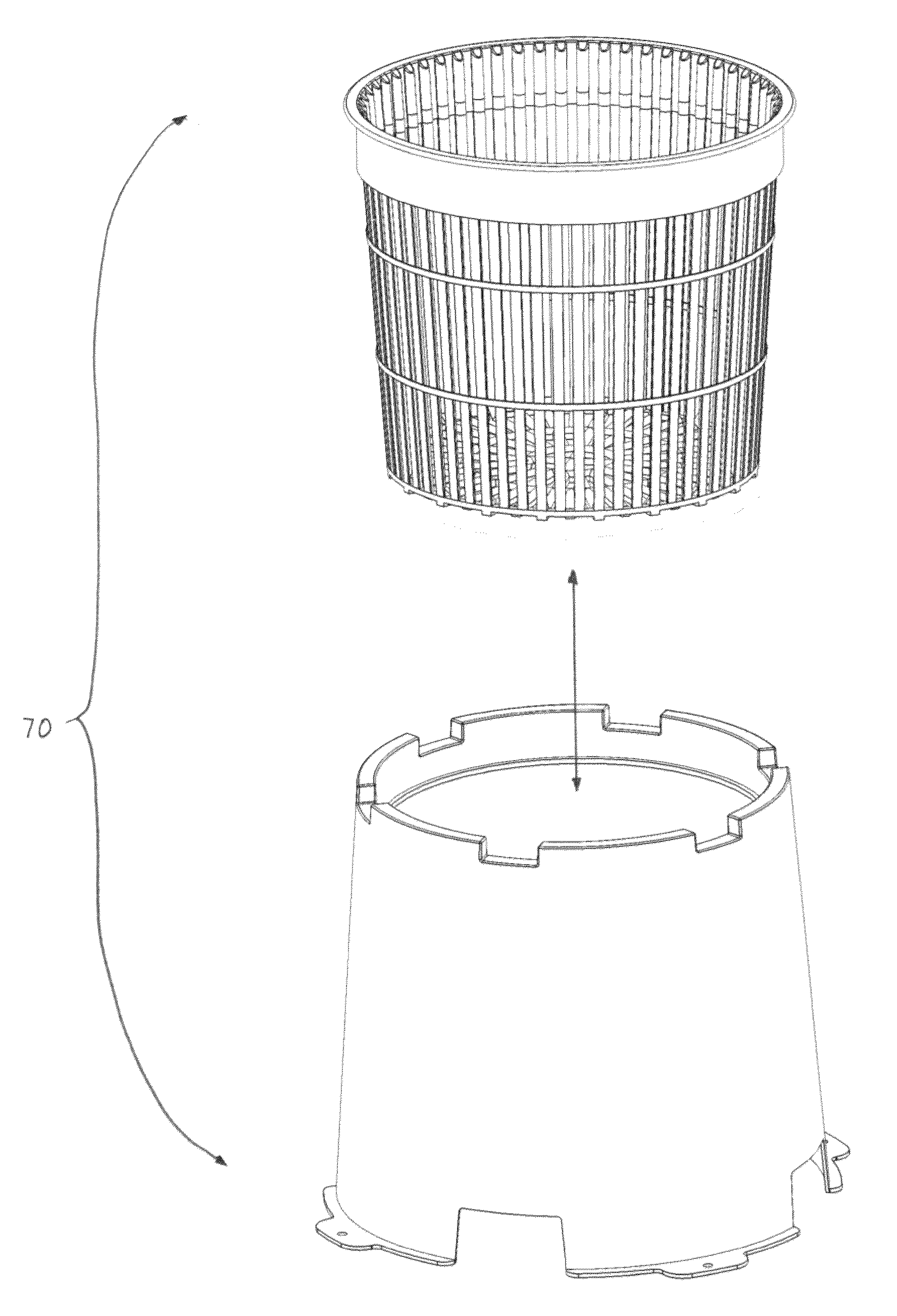
[0016]In another aspect of the present invention, a bounding system for a transplantable plant is provided for bounding a growing medium in which the transplantable plant is grown. The bounding system includes a bounding apparatus having a sheet-like sidewall framework and a bottom support, which cooperates to define a cavity, formed for receipt of the growing medium therein. The sidewall framework, having a sidewall surface area, defines a plurality of elongated, spaced sidewall apertures therebetween that collectively define a sidewall aperture area. The sidewall aperture area comprises at least about 50% of the sidewall surface area. The bottom support includes a sheet-like bottom framework having a support surface area, and defines a plurality of spaced bottom wall apertures. The bottom and bottom wall apertures are adapted to promote and encourage air root pruning of the transplantable plant proximate the bottom support when vertically oriented at a location above the ground by a sufficient distance. In accordance with the present invention, the bounding system further includes a support tray, which is comprised of a relatively solid sheet material. The support tray includes a tray top portion and a surrounding sidewall. The tray top portion supportively accommodates the bounding apparatus such that the bottom support thereof is vertically oriented at least at the sufficient distance above the ground. The surrounding sidewall and the sidewall framework define a humidifying airspace therebetween in a manner reducing rapid dry-down.
[0017]Accordingly, the support tray significantly reduces, if not eliminates, sun exposure of the exposed growing media contained at the sidewall apertures and the bottom support wall apertures significantly reducing rapid dry-down of the exposed growing media. Moreover, the air movement of the immediately surrounding the sheet-like sidewall framework is also significantly reduced, essentially creating a dead airspace (i.e., the humidifying airspace therebetween). In effect, the significant reduction of the rapid dry down, as well as the significant reduction of air movement, in this dead airspace creates a surrounding high humidity area, which further promotes air root pruning.

Problems solved by technology

The smooth-wall containers, however, tend to deflect root growth, causing it to then follow along the interior surface of the container, or deflect the root around the sidewall creating a root defect.
This often results in root circling and a stem girdling root system.
Such containers cause the primary roots to revolve around the container, which can cause significant stability problems when the tree matures.
Such poor root development and anchorage problems are especially detrimental to trees of the larger variety.
When such a plant is later installed into the landscape, it will likely fail to establish a normal root structure, and instead will have reduced uptake of water and nutrients.
Eventually abnormal growth should be obvious and could cause the plant to fail.
Damaged root systems also cause leaves to turn yellow or brown, shrivel or drop.
In all these designs, however, the side apertures are relatively small, and are not sufficiently abundant.
This is due to the fact that too large and too many apertures will not retain the soil properly, allows the water to pass through the sides too quickly, not allowing the soil to absorb moisture, and accelerates evaporation.
Although the mere presence of a side aperture or apertures do function to encourage side root growth, air-pruning of the roots, and initially reduce the incidence of spiraled or circled roots, eventually the small sidewall apertures become filled with roots or the secondary roots the encounter sidewall and deflect, causing spiraling and circling to ensue.

Method used


Image

  • Plant container assembly and method
  • Plant container assembly and method
  • Plant container assembly and method

Examples


Embodiment Construction

[0063]While the present invention will be described with reference to a few specific embodiments, the description is illustrative of the invention and is not to be construed as limiting the invention. Various modifications to the present invention can be made to the preferred embodiments by those skilled in the art without departing from the true spirit and scope of the invention as defined by the appended claims. It will be noted here that for a better understanding, like components are designated by like reference numerals throughout the various figures.

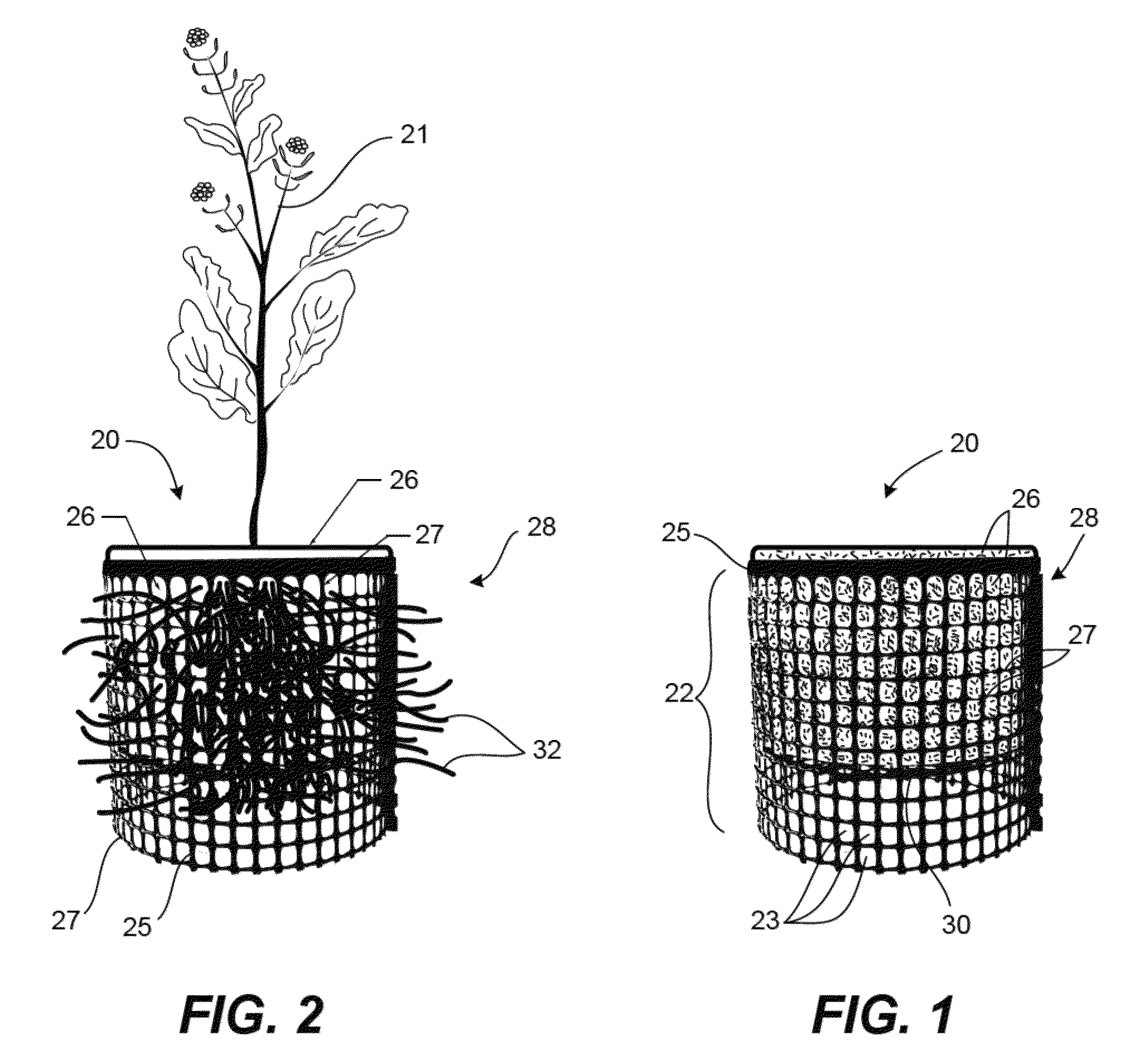
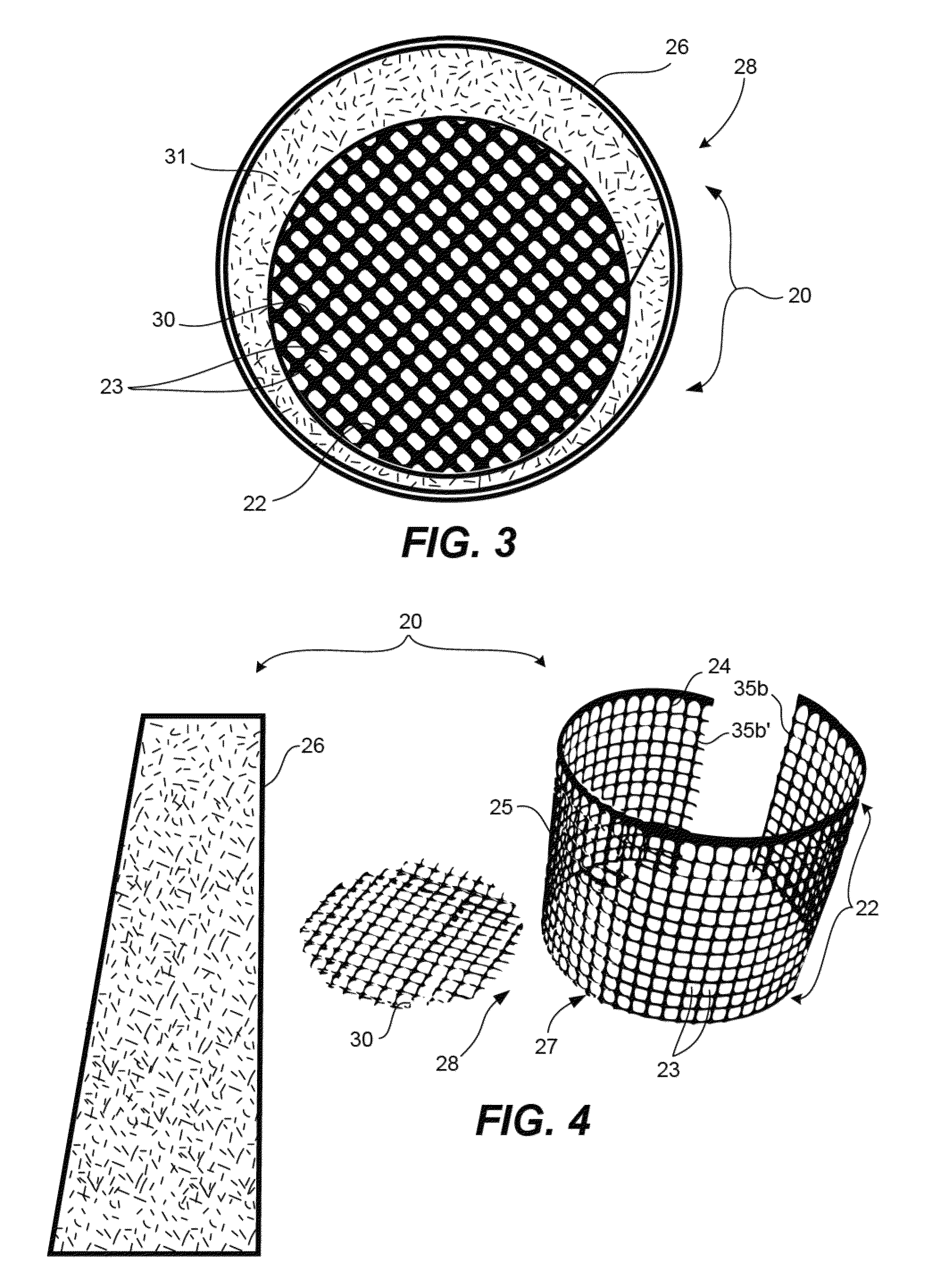
[0064]Referring now to FIGS. 1-4, a bounding apparatus, generally designated 20, is illustrated, for bounding a growing medium in which a transplantable plant 21 is grown. The bounding apparatus 20 includes a sheet-like lattice framework 22 defining a plurality of spaced apertures 23 extending through the lattice framework from an interior wall 24 to an exterior wall 25 thereof. The bounding apparatus 20 further includes a relative...


PUM


Abstract

A bounding system for a transplantable plant including a bounding apparatus and a support tray. The bounding apparatus includes a sheet-like sidewall framework defining a plurality of elongated, spaced sidewall apertures, and a bottom support having a support surface area. The bottom support is includes a sheet-like bottom framework defining a plurality of spaced bottom wall apertures. The bounding system includes a support tray comprised of a relatively solid sheet material, and having a tray top portion and a surrounding sidewall. The tray top portion defines an opening therethrough that is formed and dimensioned for supportive receipt of the bounding apparatus therein such that the bottom support thereof is vertically oriented at least at a sufficient distance above the ground to promote and encourage air root pruning of the transplantable plant proximate the bottom support. The surrounding sidewall and the sidewall framework defines a humidifying airspace therebetween in a manner reducing rapid dry-down.

Description

RELATED APPLICATIONS[0001]This application is a Continuation-In-Part of U.S. patent application Ser. No. 13 / 566,211, now U.S. Pat. No. 8,443,548, filed Aug. 3, 2012, which in turn is a Continuation of U.S. patent application Ser. No. 12 / 463,122 (now U.S. Pat. No. 8,261,488), filed May 8, 2009, both entitled “PLANT CONTAINER ASSEMBLY AND METHOD, and both naming Kempf as the inventor; which further claims priority under 35 U.S.C. §119(e) from U.S. Provisional Patent Application No. 61 / 127,030, filed May 9, 2008, and further claims priority from U.S. Provisional Patent Application No. 61 / 192,398, filed Sep. 17, 2008, both entitled “PLANT CONTAINER”, and naming Kempf as the inventor; all of which are incorporated herein by reference in their entirety and for all purposes.FIELD OF THE INVENTION[0002]The present invention relates generally to containers for growing woody perennial plants. More particularly, the present invention relates to a container base designed to encourage air root p...

Claims


Application Information

Patent Timeline
Patent Type & Authority Patents(United States)
IPC IPC(8): A01G9/10A01G9/02A01G23/04
CPCA01G9/10A01G9/1073A01G23/04A01G9/029A01G2/20
Inventor KEMPF, BRIAN J.
Owner JENSEN LARS
Learn More