Positioning device

a positioning device and positioning technology, applied in the direction of instruments, machine supports, gears, etc., can solve the problems of dislodging roller chains, affecting the accuracy of positioning, and complex and fragile geared drives, and requiring many components to perform precise positioning

Active Publication Date: 2015-11-10
THREAT SPECTRUM
View PDF3 Cites 2 Cited by
  • Summary
  • Abstract
  • Description
  • Claims
  • Application Information

AI Technical Summary

Benefits of technology

[0006]The present invention is directed towards a high precision robotic positioning platform enabling precise aiming and movement of payloads under control of one or more users. The positioning device can include a base to which it is mounted. Bases can be an immobile tripod, tall pole, edifice, or fixture in a factory assembly line, or bases can be mobile manned or unmanned vehicles, satellites, animals, or humans. A shaft is rigidly mounted to the base, and can be a semi-permanent mount or can include a toggle clamping assembly for repeated and rapid installation and removal of the positioning device from the base. A housing can rotate about the fixed shaft via enclosed drive components. The drive components can include a motor or actuator (“motor”); bearings; pulleys or gears (“gear”); and a belt, cable, roller chain, or similar linkage to transfer torque between gears. The motor can be rigidly mounted to the housing and can rotate a pulley or pinion gear (“motor gear”) directly from the coupled motor rotor or indirectly via an intermediary gearbox. This motor gear is coupled to another gear rigidly mounted to the fixed shaft (“shaft gear”), and the inter-gear coupling can be a direct meshing of the two gears' teeth or an indirect coupling via a chain, cable, or belt.
[0008]The housing of the positioning device can rotate smoothly about the fixed shaft via a bearing rigidly coupled between the shaft and housing. The bearing can have an inner ring, an outer ring and rolling or gliding bearings that are held between the inner ring and the outer ring. The housing can be rigidly coupled to either ring of the bearing. In order to provide rigidity against static and dynamic loads in axial, radial, moment, and combined directions, the bearing can have a four point contact with the inner ring and outer ring and be under a pre-load to minimize undesired play in the bearing elements. The bearing can simultaneously serve as both a bearing and rotary shaft gear in the same package when a four point contact or similarly robust bearing arrangement includes gearing on the external ring; small bearings with external gearing can be described as miniature slew bearings or externally geared turntable bearings.
[0009]The shaft gear can be a miniature slew bearing or externally geared turntable bearing and have an outer diameter of less than 12 inches and each weighing less than 5 pounds. The inventive design can also be scaled up to support a heavier housing and payloads, and can adopt bearing element and race configurations with performance attributes more suited to larger, heavier loads than the 4-pt ball bearing configuration. Larger bearing rings can adopt weight-saving construction materials such as aluminum, beryllium, and magnesium alloys while various other materials and blends can be selected, notably carbon nanotube doped materials, to optimize other performance metrics. Further weight savings can be achieved with new materials in the rolling bearing elements; for example, either balls or cylindrical rollers constructed of silicon nitride.
[0010]Payloads can be rigidly coupled to the housing and precisely rotated along with the housing about the fixed axis by control of the motor and drive components. To accommodate payloads which must not rotate with the housing, a ‘pan-through shaft’ configuration can be adopted. If the bearing is mounted around the shaft on one side of the housing, a second bearing or bushing can be mounted around the shaft on a second side of the housing opposite the first side. This secondary bearing can have a loose fit on the shaft to delegate axial loads to the more capable turntable bearing. The bearings and shaft components can align to each other with keyways and precisely located alignment pins, and an intermediary shaft coupler can compensate for any remaining shaft misalignment. The fixed shaft can be extended completely through the second side of the housing and payloads can be coupled to the end of the fixed shaft for a mounting stationary with the fixed base and thus free of the housing's rotary motion.
[0017]Human, cyborg, and AI users can control the positioning device through networks, and can collaborate and share resources through a cloud network; for example, an onboard AI within the positioning device can be tasked with analyzing payload sensors in real-time to detect and cognitively realize events of interest. Video clips and telemetry of interest can be uploaded to a database within a secure cloud, and other human or AI operators can assume control of the positioning device to investigate further and / or perform secondary data mining of the information received from it. An integrated battlespace monitoring application on another cloud resource may fuse the information from multiple positioning devices to view individual targets from multiple, overlapping angles or to secure wide areas. In another application of the invention where payloads can include mechanical arms and cameras, a team of doctors can assist patients remotely. Often patients are located within a hostile zone and a robust unmanned ground vehicular robot must endure high vibration, impacts, and harsh weather en route to the patients, then enable doctors precision motion to inspect wounds and manipulate surgical tools.

Problems solved by technology

The mechanical drive mechanisms used by robots have been geared systems such as spur, harmonic, and worm gears; however, many of these systems are very complex, requiring many components to perform precise positioning and are very heavy due to the large number of components.
Such heft is burdensome in the growing market for mobile positioning platforms, while complex and fragile geared drives have high incidences of snapped gear teeth and dislodged roller chains under the high vibration and shock experience by mobile deployed equipment.
High vibration will also excessively wear the gear teeth, increasing backlash cumulatively until the accuracy is degraded beyond what the user can tolerate.

Method used


Image

  • Positioning device
  • Positioning device
  • Positioning device

Examples


Embodiment Construction

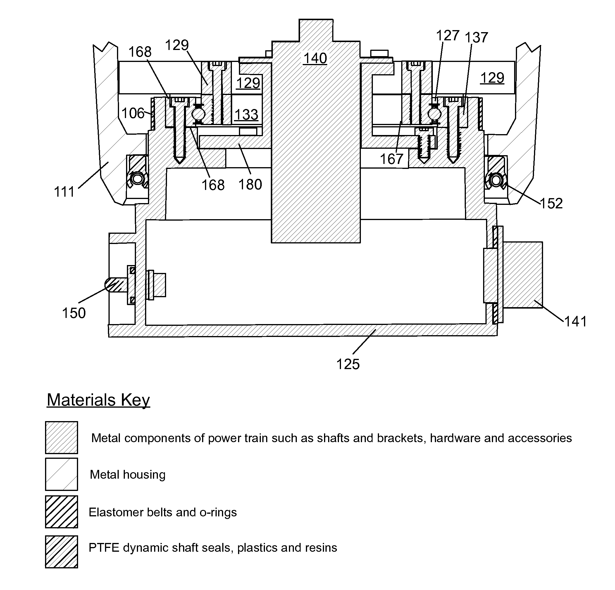
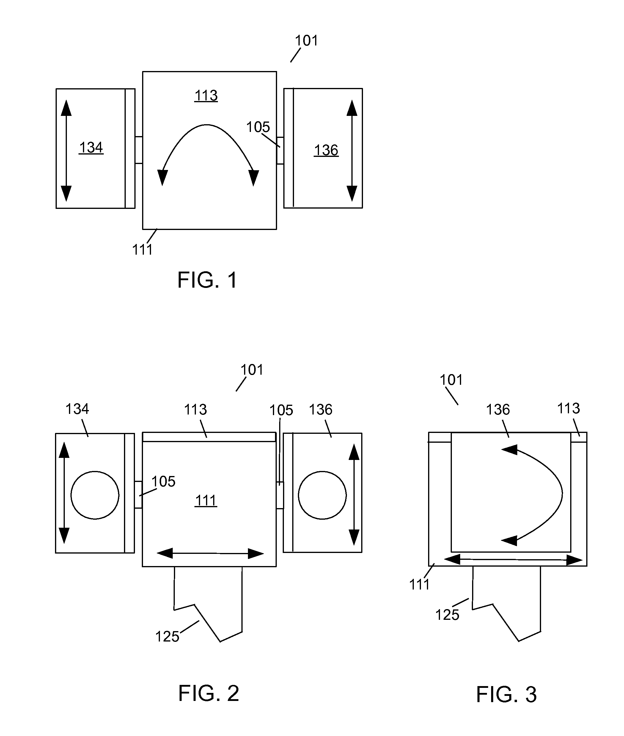
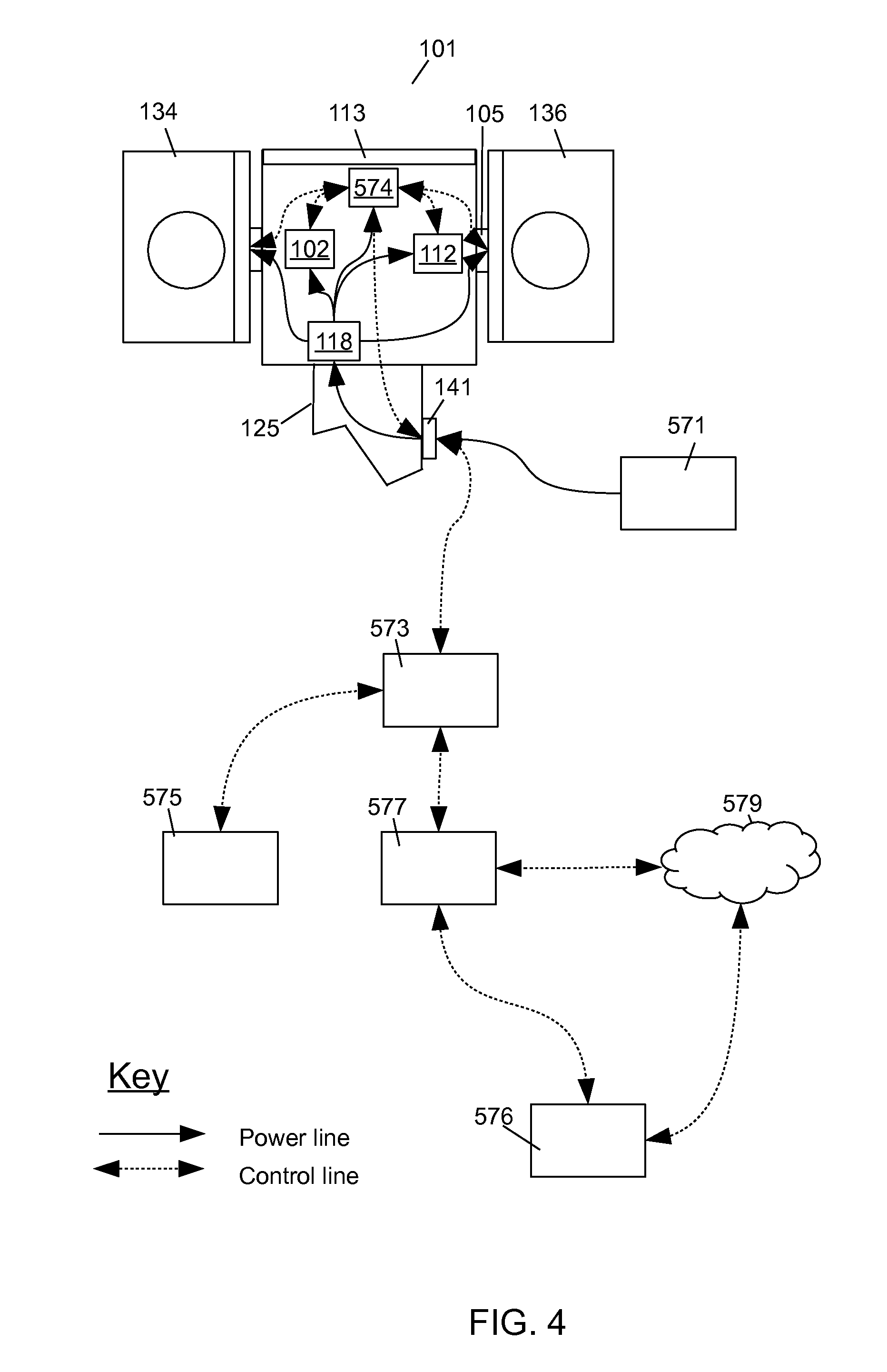
[0082]The present invention is directed towards a robotic positioning device. With reference to FIGS. 1-3, a top view of an embodiment of the robotic positioning device 101 is illustrated in FIG. 1, a front view of the positioning device 101 is illustrated in FIG. 2 and a side view of the positioning device 101 is illustrated in FIG. 3. The positioning device 101 is mounted on a pan shaft 125 and can have a first payload 134 and / or a second payload 136 rigidly coupled to opposite ends of a tilt shaft 105. The first payload 134 and the second payload 136 can be almost any type of equipment including arms, cameras, lasers pointers, laser designators, laser range finders, laser power transceivers, spotlights, covert illumination, loud speakers, antennae, radar, sensors, less-lethal weapons, lethal weapons, and any combination of such devices mounted together into a multi-sensor package. The positioning device 101 can rotate about the pan shaft 125 and the tilt shaft 105 can rotate with...


PUM


Abstract

A positioning device is used to accurately position payload devices coupled to the positioning device. The positioning device includes a housing, a tilt shaft that extends through one side or two sides of the housing. The payloads are coupled to the exposed ends of the tilt shaft and a tilt bearing is mounted between the tilt shaft and the housing. The tilt shaft position is controlled by a tilt motor that engages a toothed tilt belt to rotate the tilt shaft bearing. A pan bearing is mounted between the housing and a pan shaft. The rotational position of the housing is controlled by a pan motor which engages a toothed pan belt to rotate the housing. By controlling the pan and tilt, the payloads can be accurately moved to any rotational position.

Description

CROSS REFERENCE TO RELATED APPLICATIONS[0001]This application claims priority to U.S. Provisional Patent Application No. 61 / 640,141, “POSITIONING DEVICE,” filed on Apr. 30, 2012; U.S. Provisional Patent Application No. 61 / 800,537, “Positioning Device,” filed Mar. 15, 2013; and U.S. Provisional Patent Application No. 61 / 801,834, “POSITIONING DEVICE WITH QUICK ATTACH DETACH MOUNTING, WITH SHAFT MISALIGNMENT COMPENSATION AND BELT TENSIONING LOCK MECHANISM,” filed Mar. 15, 2013, which are hereby incorporated by reference in their entirety.FIELD OF THE INVENTION[0002]The present invention relates generally to robotic positioning devices and more particularly to a device for rotatably positioning one or more payload devices about one or more rotational axes.BACKGROUND[0003]Robots are machines that can perform tasks automatically or with guidance, typically by remote control. A robot is usually an electro-mechanical machine that is guided by computer and electronic programming. Robots can ...

Claims


Application Information

Patent Timeline
Patent Type & Authority Patents(United States)
IPC IPC(8): F16M11/04
CPCF16M11/043G03B37/02F16M11/10F16M11/18F16M11/2014F16C19/166F16C2322/39F16C19/181F16C33/581F16C2300/14F16H7/14Y10S901/39F16B2/18H04N23/00F16B2/185F16M11/041
Inventor SHANNAHAN, MICHAEL SCOTTRAY, PETER SARGON
Owner THREAT SPECTRUM
Why Eureka
Try Eureka