
Device for supporting and oscillating continuous casting moulds in continuous casting plants

Active Publication Date: 2015-11-17
ARVEDI STEEL ENG
View PDF8 Cites 2 Cited by
  • Summary
  • Abstract
  • Description
  • Claims
  • Application Information

AI Technical Summary

Benefits of technology

The present invention aims to provide a device for supporting and oscillating continuous casting molds in continuous casting plants. The device can overcome the drawbacks associated with traditional devices. The invention restrains hydraulic dampers to minimize pressure fluctuations caused by the mold's oscillation. The restraints are positioned upstream or downstream of each support, and can be associated with the connecting pipes that supply the cooling fluid to the mold. This configuration allows the device to direct vertical hydraulic forces towards the mold while dampening pressure fluctuations in the cooling fluid supply line, leading to improved heat exchange efficiency. This invention is simple, cost-effective, and doesn't require complex modifications of the supports or restraints.

Problems solved by technology

This involves the use of more and more powerful cooling systems for the moulds, which require high working pressures of the cooling fluid, for example in the order of 20 bar or higher, and high flow rates, which result in supply pipes having larger and larger cross-sections.
Therefore, the servomechanism must be designed by taking into account this dynamic balance of the forces, which results in solutions the construction and operation of which are not always satisfactory.
Another problem of known supporting and oscillating devices for continuous casting moulds is that oscillations imposed by the servomechanism to the elastic elements that hydraulically connect fixed pipes, which are generally arranged vertically upstream of the supporting device of the mould, and the movable assembly of the single support, generate pressure fluctuations in the channels formed in the supports and in the cooling circuit of the mould, thus altering the flow rate of the cooling fluid over time and potentially causing pulsating vaporization phenomena.
A reduced heat exchange can also result in the formation of cracks in the copper side walls of the mould in contact with the metal passing therethrough, as well as thermal fatigue phenomena.
However, the use of hydropneumatic accumulators is problematic, because of their overall dimensions.
Furthermore, in order to effectively reduce pressure pulsations that disturb the flow of the cooling fluid, hydropneumatic accumulators must be designed for specific frequency ranges and set at defined pressure levels, thus not being able to properly operate when the pressure of the cooling fluid varies e.g. at the discharge of the mould in function of its flow rate.

Method used


Image

  • Device for supporting and oscillating continuous casting moulds in continuous casting plants
  • Device for supporting and oscillating continuous casting moulds in continuous casting plants
  • Device for supporting and oscillating continuous casting moulds in continuous casting plants

Examples


Embodiment Construction

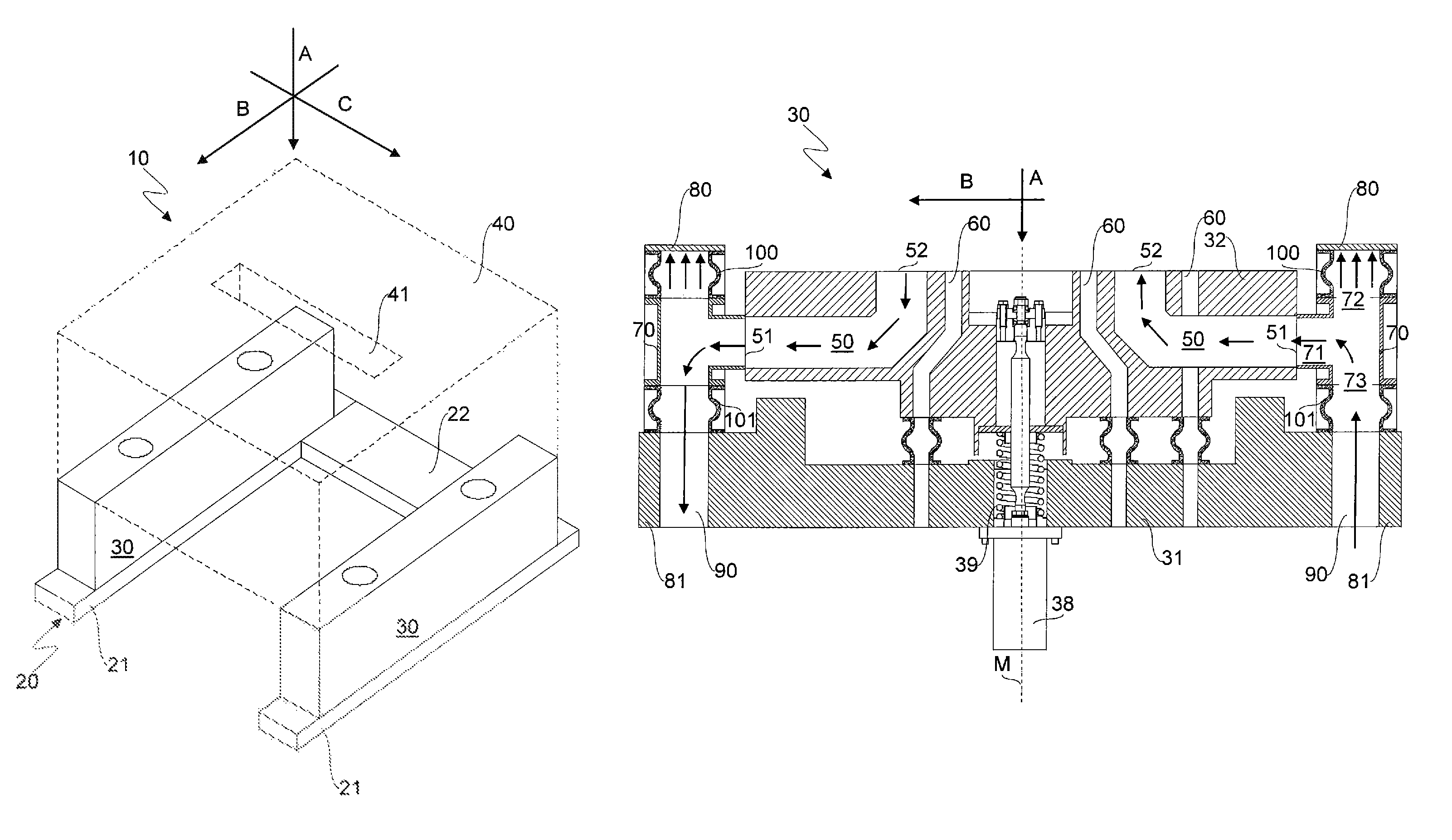
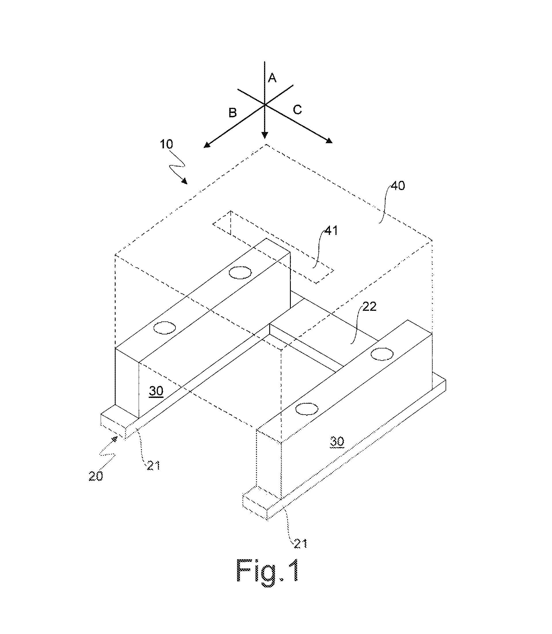
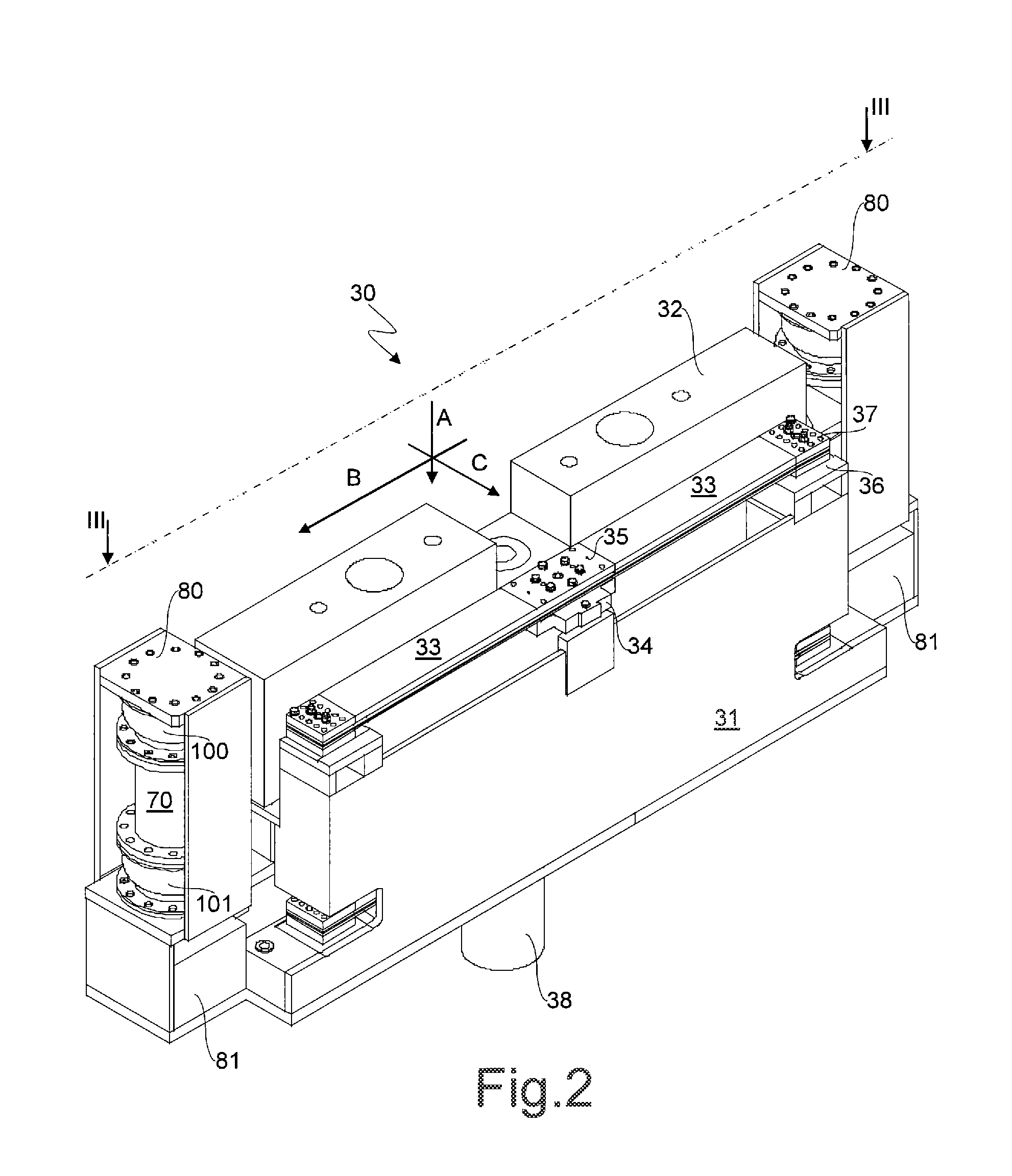
[0023]Referring to FIGS. 1 and 2, a supporting and oscillating device for continuous casting moulds of continuous casting plants for slabs is indicated by the reference numeral 10 and comprises a frame 20 adapted to be fixed on a foundation (not shown) of a continuous casting plant. The frame 20 has a U-shape and comprises in particular two parallel arms 21 connected by a crosspiece 22.

[0024]The device 10 also comprises at least one support 30 suitable to support a continuous casting mould 40, which is schematically shown in FIG. 1 by a dashed line. In the illustrated embodiment, the device 10 comprises in particular a pair of supports 30 mounted on the parallel arms 21 of the frame 20.

[0025]During operation of a continuous casting plant, metal in the liquid state, for example steel, is poured by gravity into the mould 40 in a vertical direction A, preferably but not exclusively by means of a special ceramic duct (not shown), and crosses a flow-through cavity 41 of the mould 40 thus...


PUM

PropertyMeasurementUnit
Flow rateaaaaaaaaaa
Diameteraaaaaaaaaa
Elasticityaaaaaaaaaa

Abstract

A device for supporting and oscillating continuous casting molds in continuous casting plants includes at least one support suitable to support a continuous casting mold, the support including a fixed assembly restrained to a frame of the device and a movable assembly that is slidably restrained to the fixed assembly in a vertical direction and connected to a servomechanism suitable to move it in a reciprocating manner relative to the fixed assembly along the axial direction, the movable assembly including a plurality of channels suitable to allow a flow of a cooling fluid to and from a cooling circuit of the mold, the channels being supplied by supply pipes arranged along the vertical direction. The device further includes at least one connecting pipe suitable to allow to connect a supply pipe, the connecting pipe having a T shape and including a first duct rigidly connected to the movable assembly in a horizontal direction, as well as a second and a third duct extending from the first duct in opposite ways along the vertical direction, the second and third ducts being respectively connected to first and second end portions of the fixed assembly through further axially deformable ducts and being respectively a blind duct and a flow-through duct suitable to allow the cooling fluid to flow towards the first and the second ducts. The second and third ducts, and preferably also the first duct, of the at least one connecting pipe have the same diameter of the supply pipes.

Description

CROSS-REFERENCE TO RELATED APPLICATIONS[0001]This application is a 371 of PCT / IB2012 / 057338 filed Dec. 14, 2012, which claims the benefit of Italian Patent Application No. MI2011A002292, filed Dec. 16, 2011, the contents of each of which are incorporated herein by reference.FIELD OF THE INVENTION[0002]The present invention generally relates to continuous casting plants and in particular to a device suitable to support a continuous casting mould and to allow its oscillation during a continuous casting process, with particular but not exclusive reference to the production of slabs.BACKGROUND OF THE INVENTION[0003]Continuous casting is an industrial manufacturing process wherein a metallic material in the liquid state, for example steel, is poured by gravity from a ladle into a tundish and from this into a continuous casting mould. As known, the mould of a continuous casting plant comprises an open bottom and side walls preferably but not exclusively made of copper, which, during opera...

Claims


Application Information

Patent Timeline
IPC IPC(8): B22D11/053B22D11/055
CPCB22D11/053B22D11/055
Inventor BIANCHI, ANDREA TEODOROARVEDI, GIOVANNI
Owner ARVEDI STEEL ENG
Learn More