Aircraft airfoil, and an aircraft provided with such an airfoil

a technology for airfoils and aircraft, applied in the direction of fuselages, spars/stringers, transportation and packaging, etc., can solve the problems of bird impact risk, aircraft that projects from the fuselage runs the risk of being impacted by an obstacle, and the fastener system connecting the airfoils to the fuselage of the aircraft, so as to minimize the risk of rotor damage and generate little debris

Active Publication Date: 2015-11-17
EUROCOPTER
View PDF21 Cites 4 Cited by
  • Summary
  • Abstract
  • Description
  • Claims
  • Application Information

AI Technical Summary

Benefits of technology

[0046]Furthermore, since the deflector member is not fastened to the front structure, installing the deflector member does not involve modifying the front structure. Under such conditions, the front structure does not need to be dimensioned so as to be capable of withstanding a bird impact, for example. Consequently, the front structure may be a simple skin that is easy to fabricate and of low weight, since it needs only to perform an aerodynamic function.
[0065]This characteristic makes it easier to arrange the deflector member in the empty space.

Problems solved by technology

Furthermore, such a member of an aircraft that projects from the fuselage runs the risk of being impacted in flight by an obstacle, such as a bird.
A stabilizer may be the subject of a risk of bird impact when the stabilizer projects by a non-negligible amount outwards from the aircraft.
More particularly, a bird impact runs the risk of breaking the fastener system connecting an airfoil to an aircraft fuselage, since an impact against a bird generates excessive forces on the fastener system.
The fastener system becomes deformed and, in the extreme, it may break.
However the blade disturbs the aerodynamic flow of air around the cover.
The resulting stiffening of the front structure tends to give rise to a non-negligible increase in its weight.
Furthermore, fabrication of the stabilizer is made more complex.
Nevertheless, reinforcing the front structure gives rise to a significant increase in the weight of the airfoil.
In addition, the fabrication of that airfoil and more particularly of its front structure is made more complex.

Method used


Image

  • Aircraft airfoil, and an aircraft provided with such an airfoil
  • Aircraft airfoil, and an aircraft provided with such an airfoil
  • Aircraft airfoil, and an aircraft provided with such an airfoil

Examples


Embodiment Construction

[0072]Elements present in more than one of the figures are given the same references in each of them.

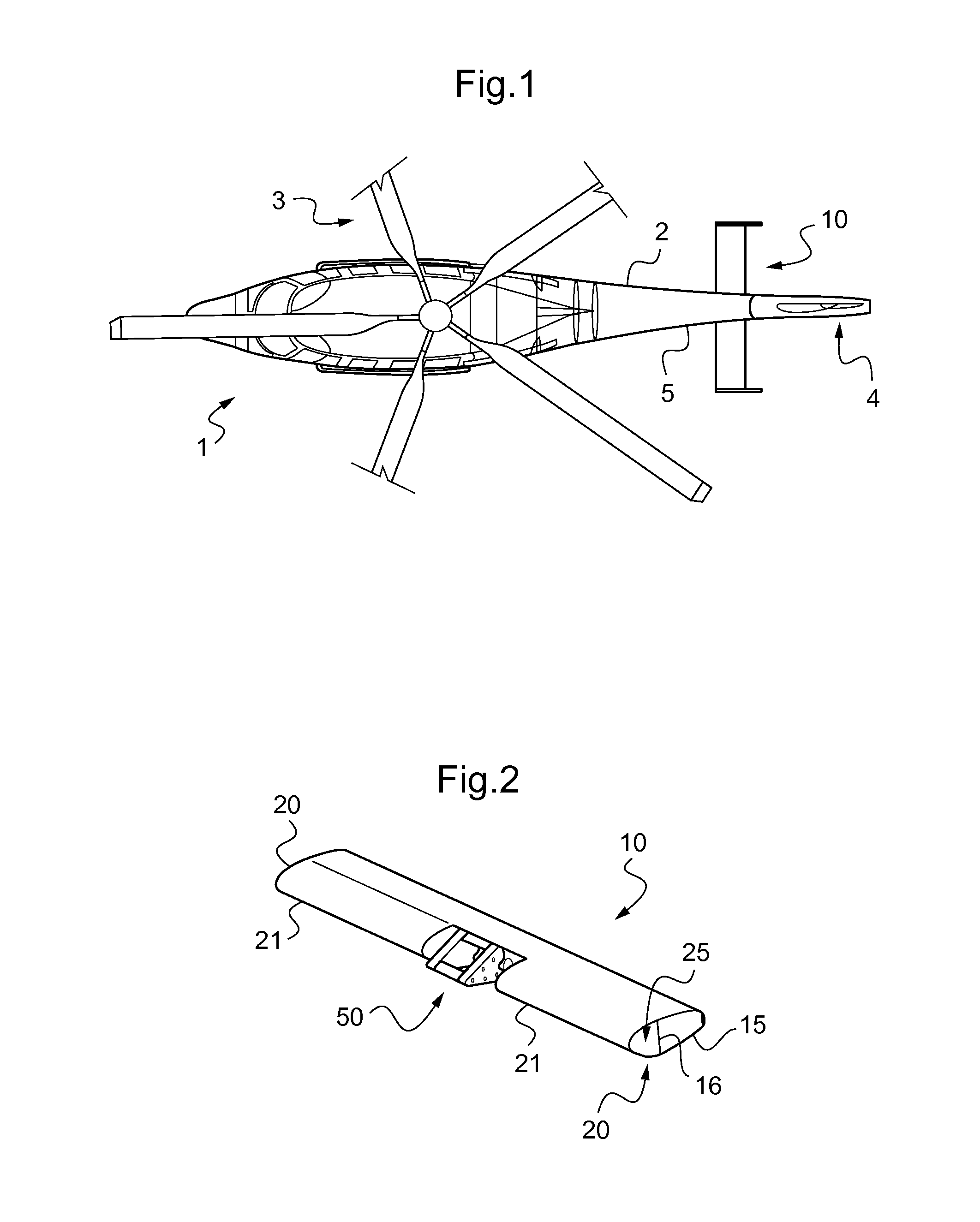
[0073]FIG. 1 shows an aircraft 1 having a fuselage 2.

[0074]The aircraft 1 may be a rotary wing aircraft. For example, the aircraft 1 may comprise a main rotor 3 for providing lift and propulsion, and also a tail rotor 4 for providing yaw control.

[0075]The aircraft 1 may also be a fixed wing aircraft.

[0076]Furthermore, the aircraft 1 has an airfoil 10 carried by the fuselage 2. Such an airfoil 10 may for example be a horizontal stabilizer fastened to a tail assembly 5 of the aircraft 1.

[0077]With reference to FIG. 2, the airfoil 10 includes a main structure 15. The main structure 15 is provided with a spar 16 secured to a fastener system 50.

[0078]The fastener system 50 thus serves to fasten the airfoil to a member of the aircraft 1, e.g. the fuselage 2.

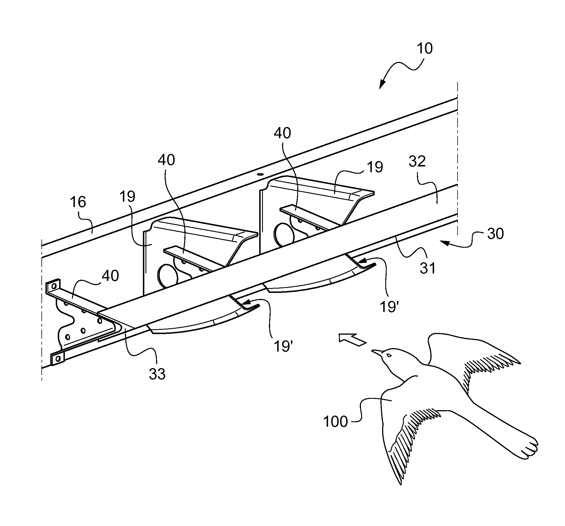
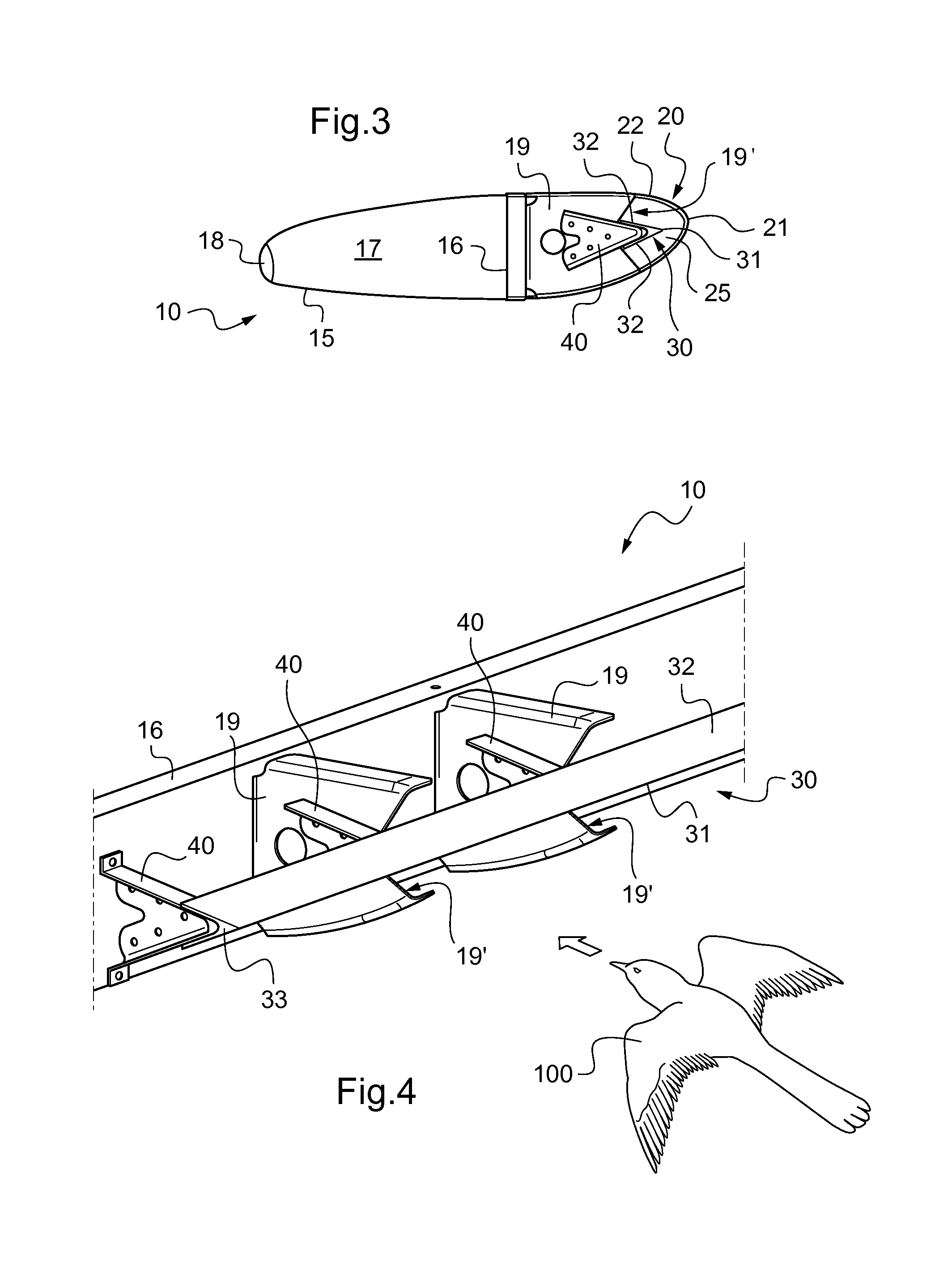
[0079]Furthermore, the airfoil 10 has a front structure 20 defining its leading edge 21.

[0080]With reference to FIG. 3, the airfoil ha...


PUM


Abstract

An airfoil (10) having a main structure (15) including at least one spar (16) and a front structure (20) forming a leading edge (21), said airfoil (10) having an empty space (25) between said main structure (15) and said front structure (20). The airfoil (10) includes a rigid deflector member (30) in said empty space (25), the deflector member being fastened to the main structure (15), said deflector member (30) having a sharp edge (31) facing towards said front structure (20) in order to deflect an external obstacle impacting against said front structure (20).

Description

CROSS REFERENCE TO RELATED APPLICATIONS[0001]The present application claims priority to French patent application FR 12 01151 filed on Apr. 19, 2012, the content of which is incorporated in its entirety by reference herein.BACKGROUND OF THE INVENTION[0002](1) Field of the Invention[0003]The present invention relates to an aircraft airfoil, and to an aircraft having such an airfoil. More particularly, the invention relates to a stabilizer, and in particular to a stabilizer for an aircraft having a rotary wing.[0004](2) Description of Related Art[0005]A stabilizer is a stationary airfoil that is generally located at the rear of an aircraft fuselage. Under such circumstances, a stabilizer is specifically designed to develop forces suitable for stabilizing and / or controlling pitching movements of the aircraft, and possibly also movements in yaw of the aircraft.[0006]A stabilizer may comprise a set of substantially horizontal airfoils and of substantially vertical airfoils.[0007]The subs...

Claims


Application Information

Patent Timeline
Patent Type & Authority Patents(United States)
IPC IPC(8): B64C3/18B64C5/02B64C3/28B64D45/00B64C27/04
CPCB64C3/185B64C3/28B64C5/02B64C27/04B64D2045/0095
Inventor LECERF, LUCMOREAU, VINCENTMARANINCHI, XAVIERSICARD, JEAN-CHARLES
Owner EUROCOPTER
Why Eureka
Try Eureka