Rocket Engine

a rocket engine and engine technology, applied in the field of rocket engines, can solve the problems of engine complexity, incongruity of walls, and complex fuel supply manifolds

Inactive Publication Date: 2005-07-12
EADS SPACE TRANSPORTATION +1
View PDF22 Cites 9 Cited by
  • Summary
  • Abstract
  • Description
  • Claims
  • Application Information

AI Technical Summary

Benefits of technology

[0003]It is an object of the present invention to overcome these disadvantages by allowing the production of a simple rocket engine, without a complex manifold, and having a very limited number of parts.

Problems solved by technology

In known rocket engines of this type, because of the very high temperatures (of the order of 3300° C.) reached in said combustion chamber, the structure of the walls is particularly complex with networks of ducts for circulating a cooling fluid which, incidentally, may be said fuel itself.
In addition, the structure of said walls is not uniform but by contrast varies along the axis of the engine, according to the temperature at that point.
Finally, particularly on account of the fact that the fuel is used as a cooling fluid and can circulate in the two opposite directions, these known engines require complex fuel supply manifolds.

Method used


Image

  • Rocket Engine
  • Rocket Engine
  • Rocket Engine

Examples


Embodiment Construction

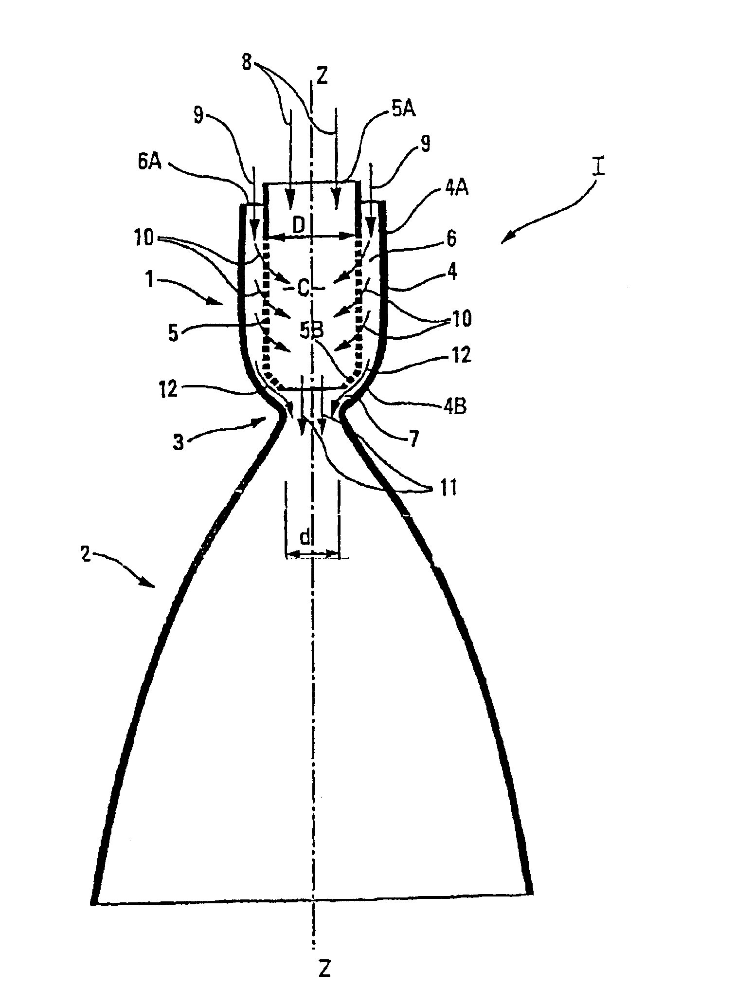
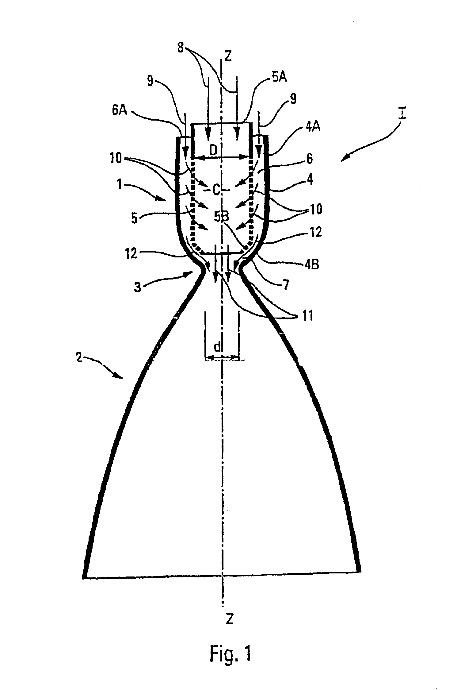
[0038]The exemplary embodiment of the rocket engine I, according to the present invention and depicted schematically in FIG. 1, comprises a combustion chamber 1 and a divergent nozzle 2 connected to one another by a throat 3. The longitudinal axis of the engine I bears the reference Z—Z.

[0039]The combustion chamber 1 comprises an outer wall 4, of which the part 4A, opposite the nozzle 2, is roughly cylindrical, whereas the part 4B of the outer wall 4, arranged at the same end as said nozzle 2, is convergent to connect with the throat 3. Thus, the outer wall 4, the throat 3 and the nozzle 2 are in continuity and able to constitute a single piece.

[0040]The combustion chamber 1 additionally comprises a porous inner wall 5, the axis of which is coincident with the axis Z—Z and which is arranged inside the outer wall 4, forming with the latter a cylindrical intermediate space of annular cross section 6. The porous inner wall 5 is also roughly cylindrical, and its diameter D is greater th...


PUM


Abstract

The invention concerns a rocket engine wherein the combustion chamber includes at least one first monolithic component made of a thermostructural composite material comprising a porous wall through which the fuel is introduced in the core of the combustion chamber. A small part of the fuel is directed towards the neck for it to be cooled.

Description

FIELD OF THE INVENTION[0001]The present invention relates to a rocket engine comprising a combustion chamber in which a fluid (liquid or gaseous) fuel, for example hydrogen, and a fluid (liquid or gaseous) oxidizer, for example oxygen, are burnt, said combustion chamber being connected to a divergent nozzle through which the gases resulting from the combustion escape.BACKGROUND OF THE INVENTION[0002]In known rocket engines of this type, because of the very high temperatures (of the order of 3300° C.) reached in said combustion chamber, the structure of the walls is particularly complex with networks of ducts for circulating a cooling fluid which, incidentally, may be said fuel itself. Examples of known walls are described, for example, in documents FR-A-2 773 850, FR-A-2 774 432, FR-A-2 791 589. In addition, the structure of said walls is not uniform but by contrast varies along the axis of the engine, according to the temperature at that point. Finally, particularly on account of t...

Claims


Application Information

Patent Timeline
Patent Type & Authority Patents(United States)
IPC IPC(8): F02K9/52F02K9/97F02K9/64F02K9/00
CPCF02K9/52F02K9/64F02K9/97F05D2240/1281
Inventor CALABRO, MAX
Owner EADS SPACE TRANSPORTATION
Why Eureka
Try Eureka