Methods for improved monitor and control of lithography processes

Active Publication Date: 2015-11-17
KLA TENCOR CORP
View PDF133 Cites 9 Cited by
  • Summary
  • Abstract
  • Description
  • Claims
  • Application Information

AI Technical Summary

Benefits of technology

[0006]No other information on lens quality is collected. The exception is that vertical and horizontal features may be looked at separately, which could indicate an astigmatism problem if there is a marked offset between the two. For example, the CD of horizontal and vertical features, usually at fixed CD and pitch but sometimes at a

Problems solved by technology

The errors may include dose errors, f

Method used


Image

  • Methods for improved monitor and control of lithography processes
  • Methods for improved monitor and control of lithography processes
  • Methods for improved monitor and control of lithography processes

Examples


Embodiment Construction

[0027]State of the art lenses cost millions of dollars, and replacing a lens may not be possible in the user's fabrication facility (“fab”) thereby requiring that the entire exposure tool is shipped back to the supplier. Even if the lens can be replaced or adjusted in the fab, it will require the exposure tool to be out of production for an extended period of time, resulting in a serious financial loss for the user. It is, therefore, imperative that whatever method is used to qualify lens performance, the user must be able to unambiguously determine if the lens itself has actually degraded to the point where it is unusable for leading edge production.

[0028]The imaging performance of any optical system is critically dependent upon the material being exposed being at the correct focal point of the imaging system. For a large field lens, this means that not only does the mean focus position have to be set correctly, but also the imaging field must not be tilted in any way relative to t...


PUM


Abstract

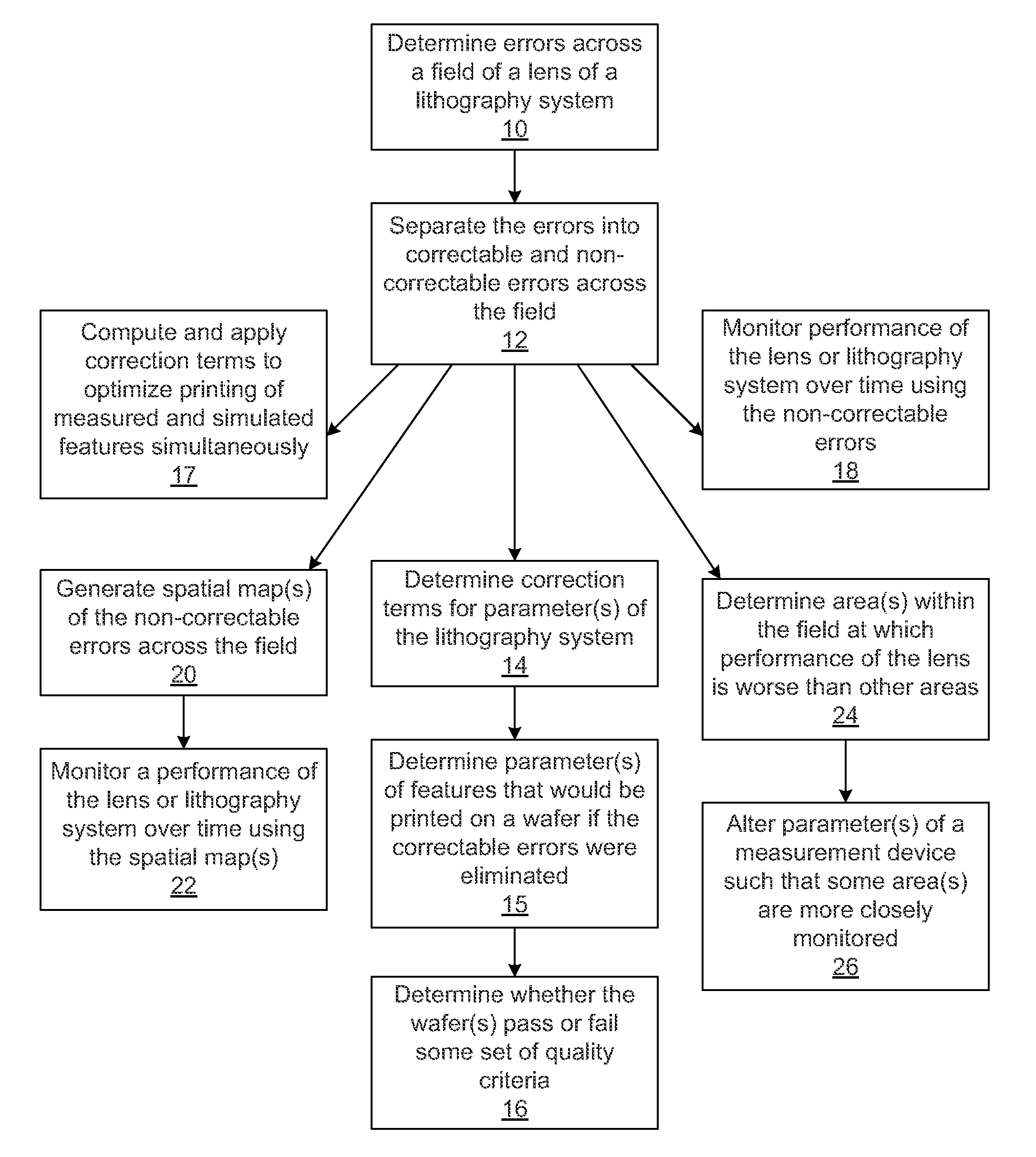
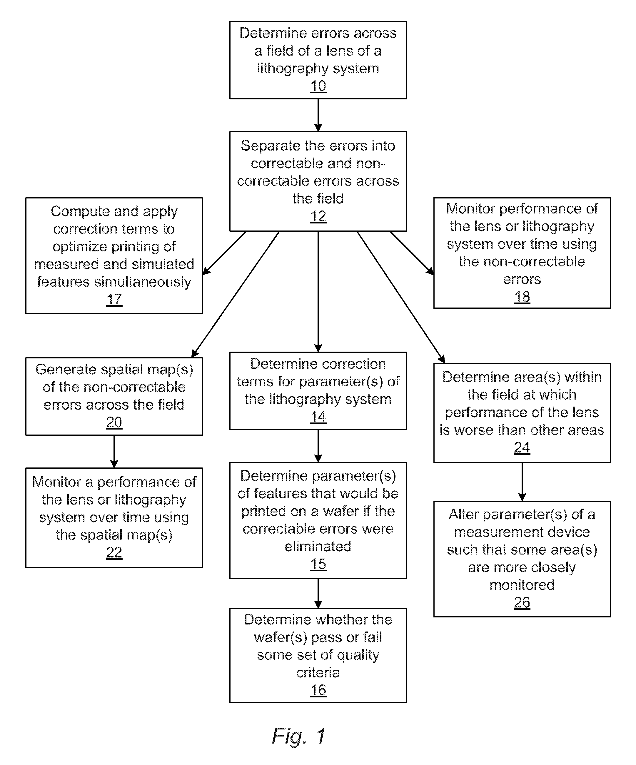
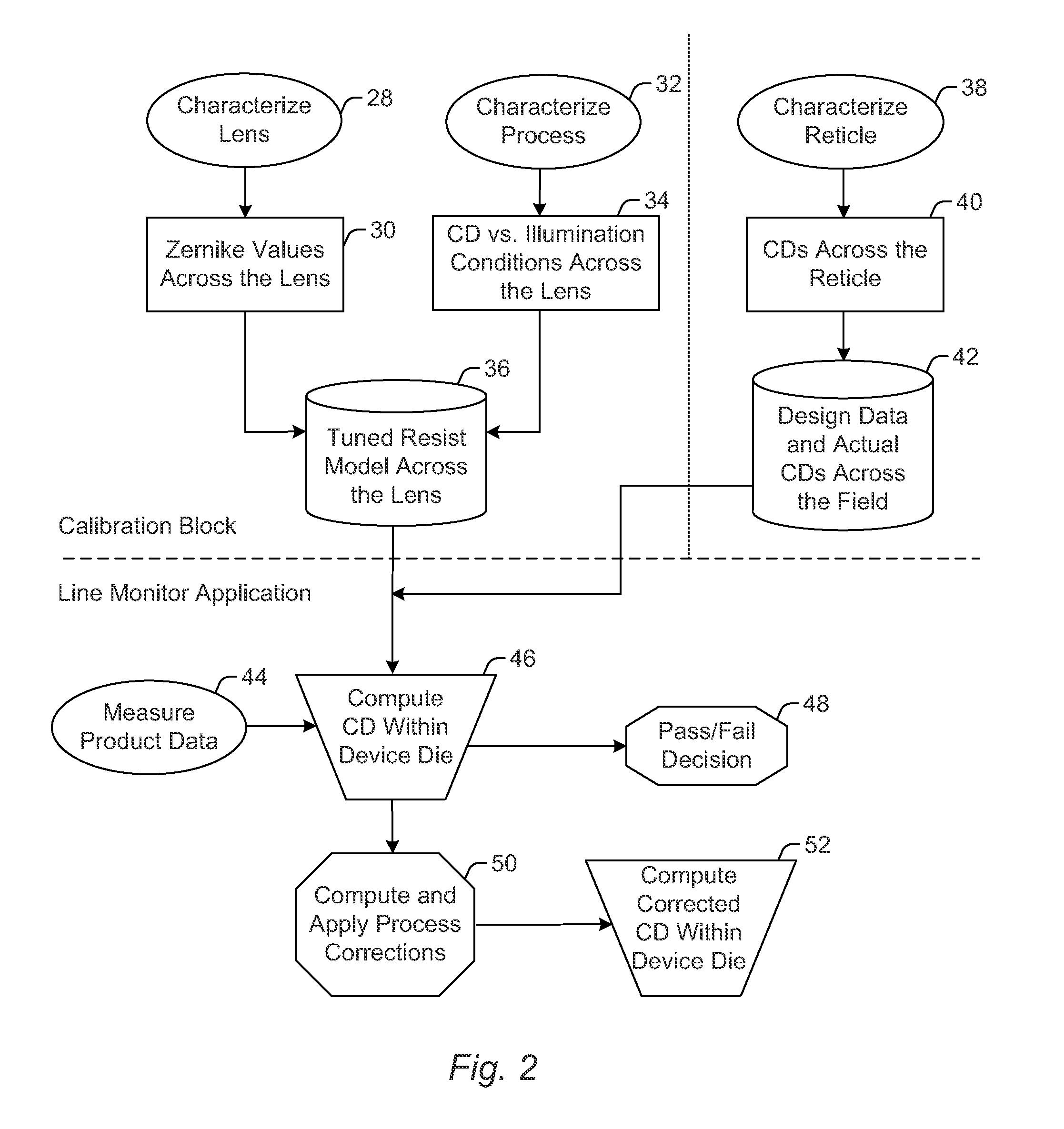
Various computer-implemented methods are provided. One method includes determining errors across a field of a lens of a lithography system based on wafer measurements. In addition, the method includes separating the errors into correctable and non-correctable errors across the field. The errors may include dose errors, focus errors, or dose and focus errors. In another embodiment, the method may include determining correction terms for parameter(s) of the lithography system, which if applied to the parameter(s), the correctable errors would be eliminated resulting in approximately optimal imaging performance of the lithography system. Another method includes controlling one or more parameters of features within substantially an entire printed area on a product wafer using a limited number of wafer measurements performed on a test wafer. The wafer measurements may be performed on a first feature type, and the features that are controlled may include a second, different feature type.

Description

CROSS-REFERENCE TO RELATED APPLICATIONS[0001]This application is a divisional of U.S. patent application Ser. No. 10 / 778,752 entitled “Methods for Improved Monitor and Control of Lithography Processes,” filed Feb. 13, 2004, which is incorporated by reference as if fully set forth herein.BACKGROUND OF THE INVENTION[0002]1. Field of the Invention[0003]The present invention generally relates to methods and systems for improved monitor and control of lithography processes. Certain embodiments relate to a computer-implemented method for separating errors into correctable and non-correctable errors across a field of a lens of a lithography system. Other embodiments relate to a computer-implemented method for controlling one or more parameters of features within substantially an entire printed area on a product wafer.[0004]2. Description of the Related Art[0005]The performance of a lithography system lens has an impact on the features that are printed by the lithography system. Currently, ...

Claims


Application Information

Patent Timeline
IPC IPC(8): G06F19/00G05B19/418G06Q10/06
CPCG06Q10/06G05B19/41875G03F7/70525G03F7/70591G03F7/70616
Inventor MACK, CHRISPREIL, MOSHE E
Owner KLA TENCOR CORP
Why Eureka
Try Eureka