Mechanical massage and traction apparatus

a traction apparatus and mechanical technology, applied in the field of mechanical massage and traction apparatus, can solve the problems of many individuals' stress, many negative side effects, and changes that have occurred over the years, and achieve the effects of safe establishment of an appropriate amount of traction, substantial and predictable traction, and convenient automatic and proper patient positioning

Active Publication Date: 2015-11-24
PETERSON PETER W +1
View PDF1 Cites 10 Cited by
  • Summary
  • Abstract
  • Description
  • Claims
  • Application Information

AI Technical Summary

Benefits of technology

[0019]A first object of the invention is to provide relief from improper or hunched posture, cervical spondylosis, cervical-muscular strains or knots, tension, and other undesirable cervical disorders or complications. A second object of the invention is to enable even an inexperienced user to safely establish an appropriate amount of traction. Another object of the present invention is for the apparatus to produce substantial and predictable traction that is primarily determined at the time of design, and that is independent of a surface upon which the patient and apparatus may rest. A further object of the invention is to facilitate automatic and proper patient positioning. Yet another object of the present invention is to provide body engaging members that are removable and replaceable for both adjustment for body size or dimension and also for repair or maintenance. An additional object of the present invention is to generate increased application forces in selected specific patient regions while avoiding application forces in other specific patient regions. Another object of the present invention is to provide an apparatus which meets the foregoing objectives while being durable, easily cleaned, and easily maintained.

Problems solved by technology

While the modern world provides many opportunities and benefits that did not exist in years past, the results of the changes that have occurred over the years are not always as beneficial as one might hope.
While the modern world frees us from the dangers and unpredictability of the hunting and gathering lifestyle of our ancestors, which many people are quite grateful for, there are negative side effects that have come with the changes.
One striking change is the general pace of life and pressures associated therewith, which leads to much stress in many individuals.
Unfortunately, the adverse health effects associated with what is often a more sedentary lifestyle, such as may be found in the confines of an office or cubicle, include such issues as a lack of or greatly reduced physical activity that could otherwise alleviate the adverse affects of stress and a seeming endless confinement to various chairs, seats and other body supports.
This combination often leads to tension, knots, fatigue and other undesirable musculo-skeletal phenomena in many individuals.
This puts substantial stress on a person's neck.
In addition, certain medical conditions such as cervical spondylosis and migraine headaches produce moderate to severe discomfort in the cervical region of the afflicted individual.
As a result, the masseuse or chiropractor is unable to tend to other patients in need during the provision of neck services, driving the costs for such treatments up, and, again, requiring not only diagnostic skill by the professional but also significant manual work.
While these devices are capable of providing relief to certain individuals in carefully controlled situations, there are a number of drawbacks associated with pneumatic devices.
The first and most obvious drawback is the relative fragility of the apparatus, which is prone to accidental punctures and leaks.
However, a second and potentially more serious drawback is the inability of an inexperienced user to accurately determine the appropriate amount of traction to generate, which creates the associated risk of too great or too little traction force being applied by the user of the apparatus.
Clearly, just a few pounds of internal pressure within the pneumatic device can undesirably lead to harmful forces being generated within the cervical region of the patient.
Finally, owing to the necessary compliance of the pneumatic device, there is no real opportunity to generate increased patient application forces in selected specific regions while avoiding application forces in other specific regions.
While potentially more durable than the pneumatic counterparts, these mechanical apparatus suffer from similar risks in terms of a patient's ability to readily determine appropriate application forces.
Unfortunately, a surprising number of the prior weight-induced traction devices achieve traction simply by draping the body part over a domed or elevated member.
This type of traction is of less benefit to a patient, owing to the necessary curvature of the spine about the support.
However, since the fingers are relatively small and densely packed, the amount of maximum traction is quite limited, and the actual traction obtained is very subject to final positional movements by the patient.
Consequently, predictable traction forces remain quite elusive.
Additionally, these apparatus are extremely sensitive to proper patient positioning, and yet there is little to assist the patient with such positioning.
While these pillows can be used to create a predictable amount of traction for a given weight load, these apparatus only provide engagement with the person's head, presumably depending upon the person resting upon a suitable surface.
This means that the traction is unpredictably distributed throughout the person's vertebrae.

Method used


Image

  • Mechanical massage and traction apparatus
  • Mechanical massage and traction apparatus
  • Mechanical massage and traction apparatus

Examples


Embodiment Construction

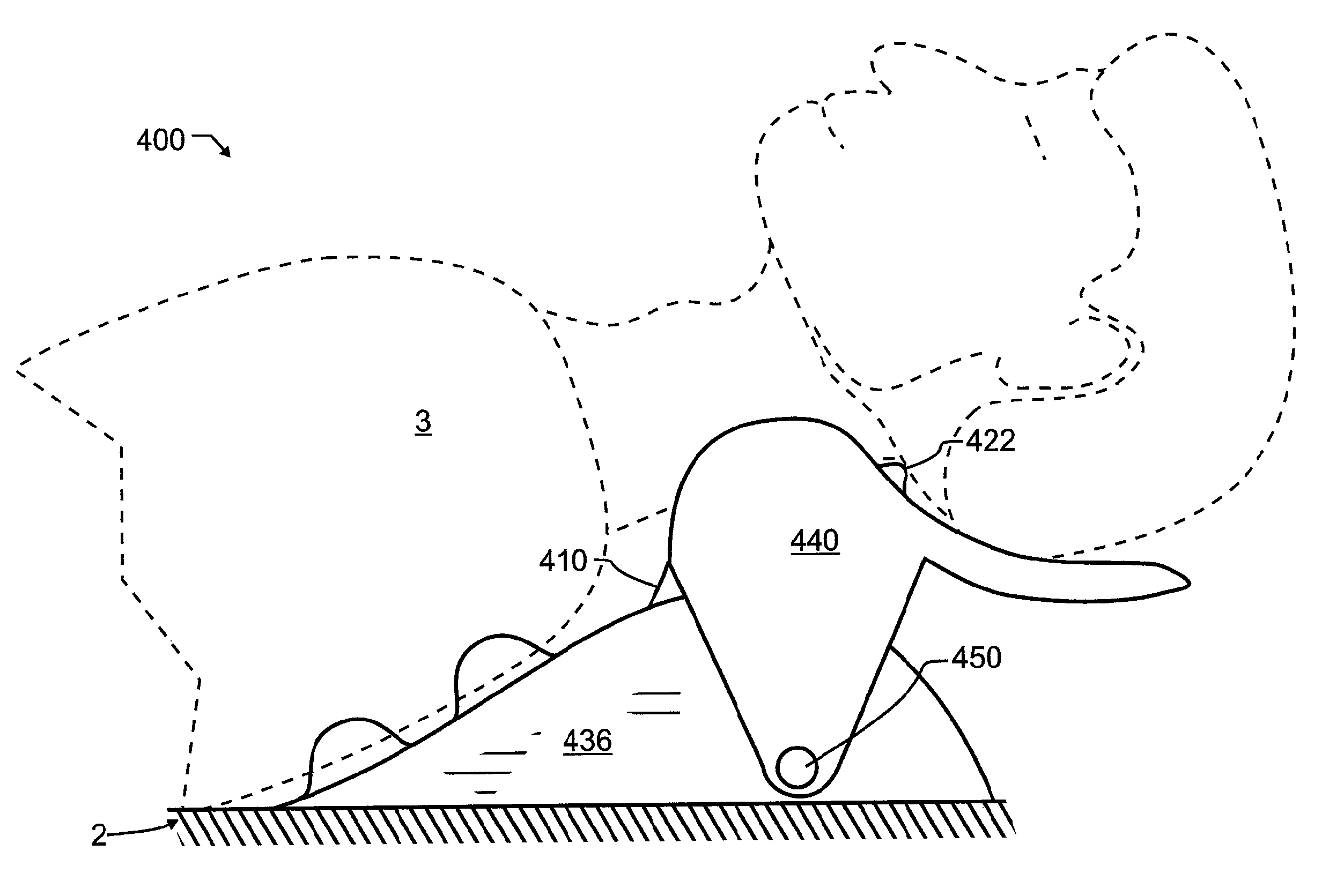
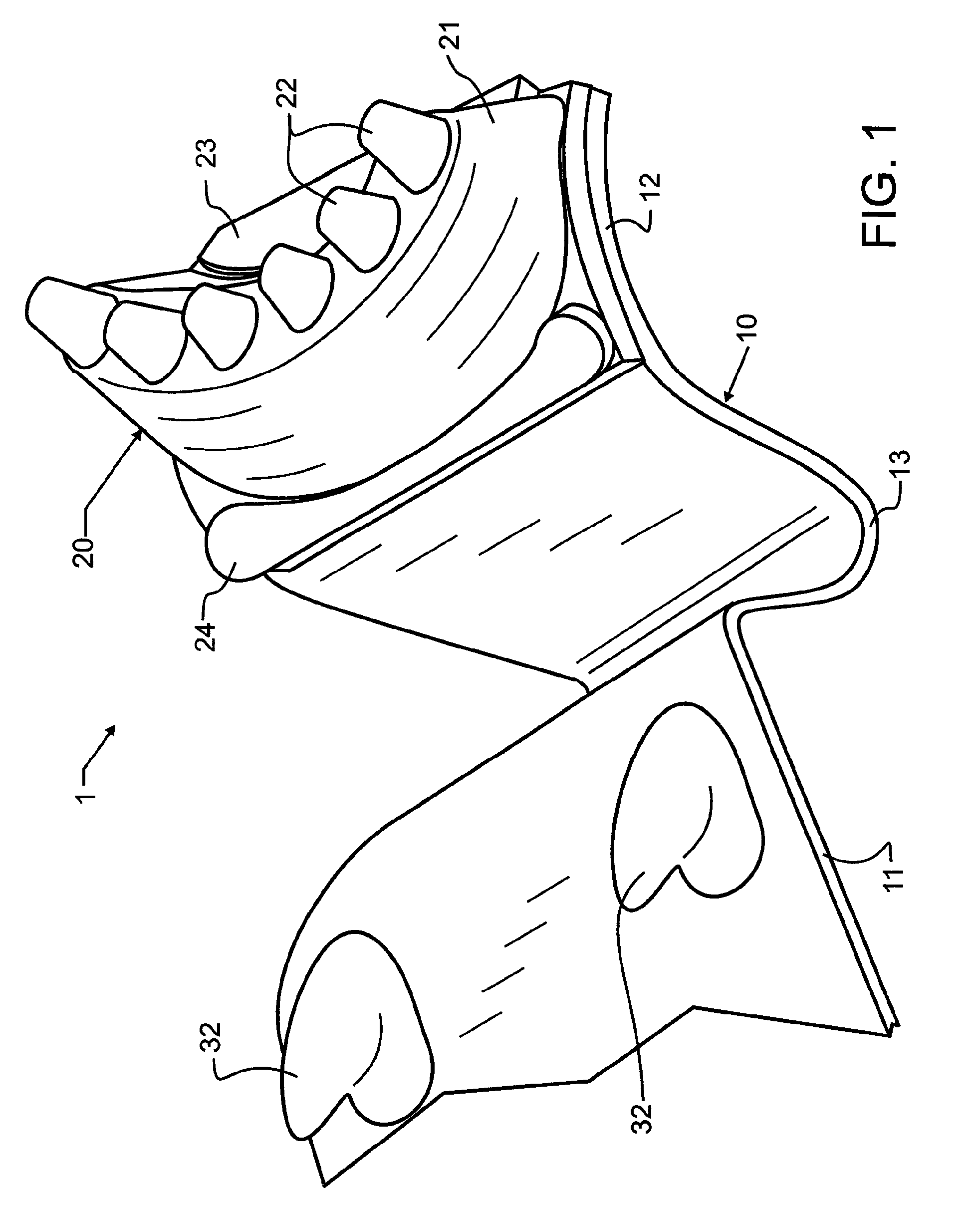
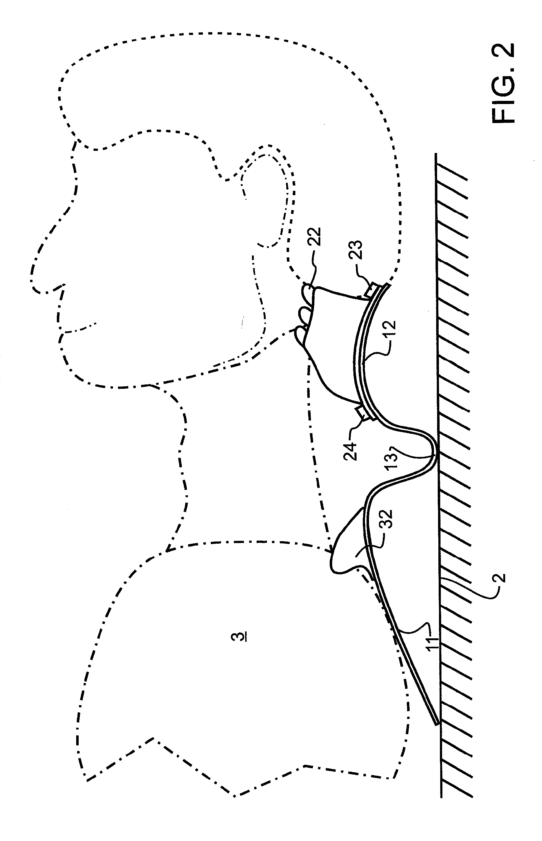
[0040]Various embodiments of apparatus designed in accord with the present invention have been illustrated in the various figures. The embodiments are distinguished by the hundreds digit, and various components within each embodiment designated by the ones and tens digits. However, many of the components are alike or similar between embodiments, so numbering of the ones and tens digits have been maintained wherever possible, such that identical, like or similar functions may more readily be identified between the embodiments. If not otherwise expressed, those skilled in the art will readily recognize the similarities and understand that in many cases like numbered ones and tens digit components may be substituted from one embodiment to another in accord with the present teachings, except where such substitution would otherwise destroy operation of the embodiment. Consequently, those skilled in the art will readily determine the function and operation of many of the components illust...


PUM


Abstract

A mechanical massage and traction apparatus provides patient weight-induced cervical traction and particular stimulation of distinct pressure points along a patient's shoulders and occipital ridge. A fixed base provides at least two shoulder-engaging members that preferably firmly engage with and massage the patient's shoulders. Pivotally coupled to the base is a head support that includes a plurality of occipital ridge engaging fingers that preferably firmly engage with and massage the patient's occipital ridge. A spring between the base and head support operatively flexes under the weight of the patient's head and shoulders, and thereby increases a distance between the shoulder-engaging members and occipital ridge support, to operatively produce traction in the patient's cervical vertebrae. The upper torso support operatively contacts an underlying support surface, and the occipital ridge support operatively floats above the underlying support surface.

Description

CROSS REFERENCE TO RELATED APPLICATIONS[0001]This application claims the benefit under 35 USC 119(e) of U.S. provisional 61 / 801,574, filed Mar. 15, 2013, and is a continuation-in-part of U.S. application Ser. No. 13 / 176,739 filed Jul. 5, 2011 and co-pending herewith, the contents of each incorporated herein by reference in entirety.BACKGROUND OF THE INVENTION[0002]1. Field of the Invention[0003]This invention pertains generally to chiropractic or osteopathic implements for restoring or tending to restore a portion of the body to its normal position or to a more proper position, and more particularly to a positioner for a recumbent user comprising a formed element beneficial to the cervical spine when a patient lays supine upon the element.[0004]2. Description of the Related Art[0005]While the modern world provides many opportunities and benefits that did not exist in years past, the results of the changes that have occurred over the years are not always as beneficial as one might ho...

Claims


Application Information

Patent Timeline
Patent Type & Authority Patents(United States)
IPC IPC(8): A61F5/00A61F5/04A61H39/04
CPCA61F5/04A61H39/04A61F5/01A61F5/3707A61H2201/1614A61H1/0218A61H1/0296A61H2201/1284A61H2201/1604A61H2203/0456
Inventor PETERSON, PETER W.BLAISDELL, GEORGE H.
Owner PETERSON PETER W
Why Eureka
Try Eureka