Steering apparatus

a technology of steering apparatus and output shaft, which is applied in the direction of hoisting equipment, transportation and packaging, cycles, etc., can solve the problem of relativly large and achieve the effect of reducing the bending load applied to the output sha

Active Publication Date: 2015-11-24
HITACHI ASTEMO LTD
View PDF11 Cites 17 Cited by
  • Summary
  • Abstract
  • Description
  • Claims
  • Application Information

AI Technical Summary

Benefits of technology

[0033]According to the present invention, it is possible to provide the steering apparatus in which a bending load applied to the output shaft is reduced, and an appropriate backlash is formed between the worm and the worm wheel.

Problems solved by technology

However, the motor-driven power steering apparatus in the related art has a problem in that since the arm stopper mechanism in the related art is not configured to prevent a bending load from being applied to the output shaft, a relatively large bending load may be applied to the output shaft, which will be described below.

Method used


Image

  • Steering apparatus
  • Steering apparatus
  • Steering apparatus

Examples


first embodiment

[0061]Hereinafter, the configuration of an arm stopper mechanism 160 (refer to FIG. 2) of a motor-driven power steering apparatus 101 according to a first embodiment will be described. Here, the characteristics of the arm stopper mechanism 160 according to the first embodiment will be described in the following sequence for descriptive purposes.

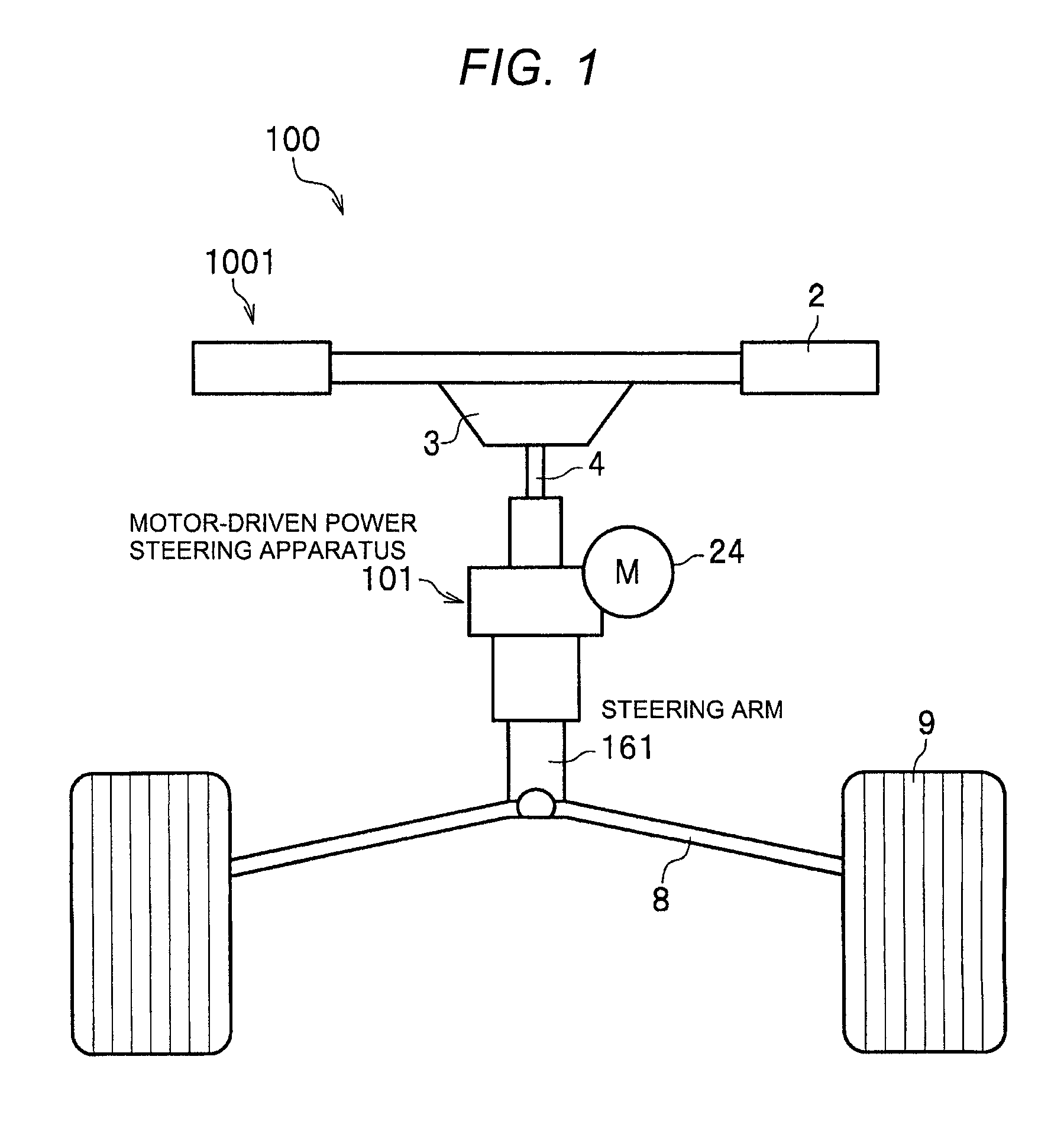
[0062]1: Schematic Configurations of Saddle-type Vehicle and Motor-driven Power Steering Apparatus

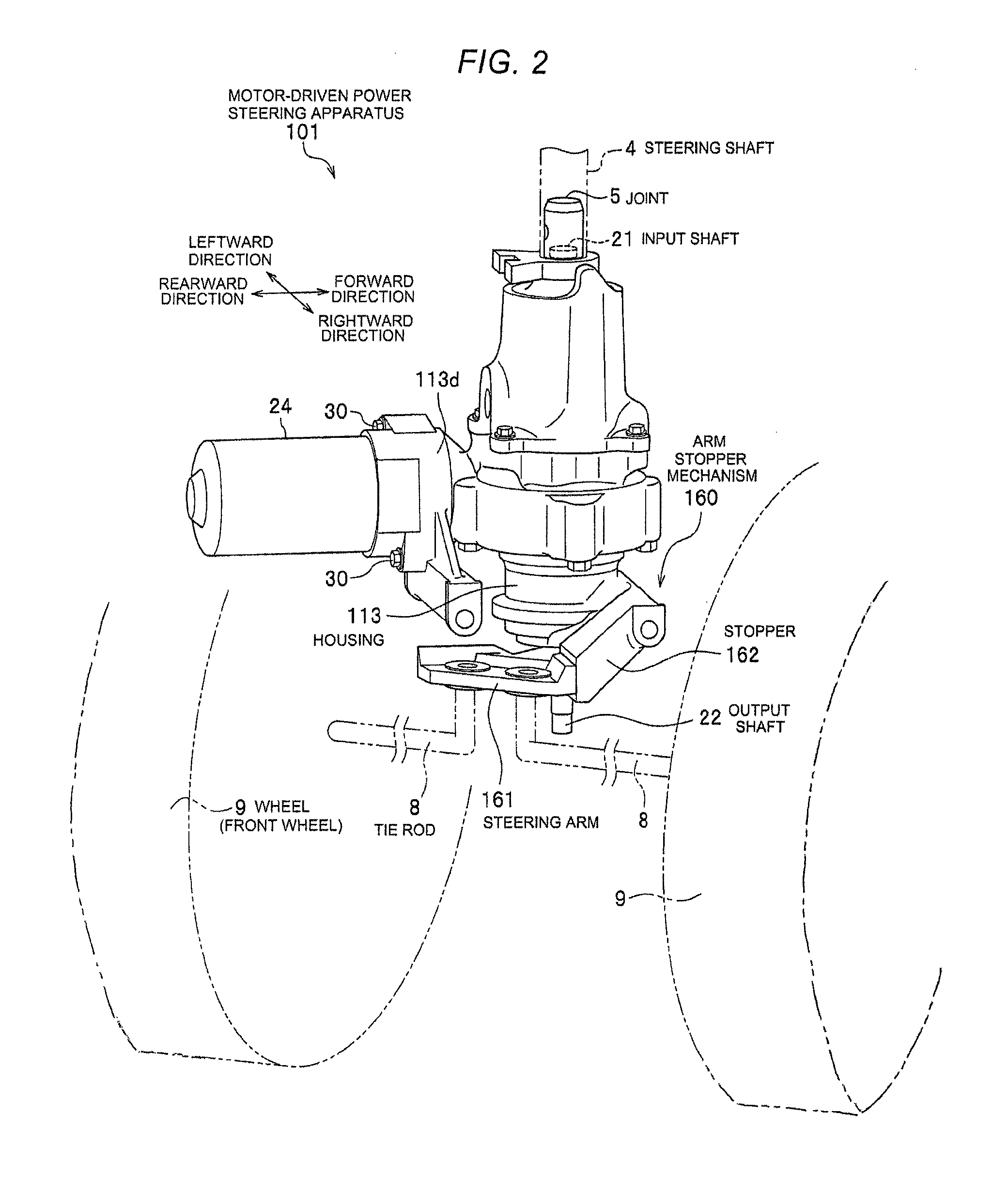
[0063]2: Schematic Configuration between Steering Arm and Wheels (Front Wheels)

[0064]3: Load Vector Applied to Steering Arm

[0065]4-1: Configuration of Arm Stopper Mechanism According to Comparative Example

[0066]4-2: Load Vectors Applied to Main Portions of Arm Stopper Mechanism According to Comparative Example

[0067]5: Relationship between Input Load Vector, and Striking Load Vector, and Bending Load Vector

[0068]6-1: Configuration of Arm Stopper Mechanism According to First Embodiment

[0069]6-2: Load Vectors Applied to Main Portions of Arm Stopper ...

second embodiment

[0215]In the arm stopper mechanism 160 according to the first embodiment, the striking surfaces 176 are respectively provided in the side portions of the main body (portion to which the tie rods 8 are attached) of the steering arm 161. In the configuration of the steering arm 161, the striking portions 174 with the striking surface 176 project outward (in a turning direction) so that the maximum steering angle of the handlebars 2 is defined.

[0216]In contrast, in the configuration of an arm stopper mechanism 260 according to a second embodiment, the striking portions do not project outward.

Configuration of Arm Stopper Mechanism According to Second Embodiment

[0217]Hereinafter, the configuration of the arm stopper mechanism 260 according to the second embodiment will be described with reference to FIGS. 16 to 18. FIG. 16 is a schematic bottom view illustrating the configuration of the arm stopper mechanism 260. FIGS. 17A to 17C are schematic bottom views illustrating the configuration ...


PUM


Abstract

A steering apparatus includes: an output shaft that outputs a steering force to wheels of a vehicle; a steering arm which turns about the output shaft, and to which two tie rods, to which the wheels are respectively connected, are attached; a stopper which is provided in a vicinity of the output shaft, and restricts an angle of the turning of the steering arm; a worm wheel that is fixed to the output shaft; a worm that is driven by a motor, and meshes with the worm wheel; a bearing that rotatably support the worm; a housing that holds the bearing; and a worm damper that is provided at an axial inner side or an axial outer side of the bearing in an axial direction of the worm, and is elastically deformable so as to move the worm in the axial direction, as defined herein.

Description

CROSS-REFERENCE TO RELATED APPLICATIONS[0001]This application claims the benefit of Japanese Patent Application JP 2014-195767, filed Sep. 25, 2014, the entire content of which is hereby incorporated by reference, the same as if set forth at length.BACKGROUND OF THE INVENTION[0002]1. Field of the Invention[0003]The present invention relates to a steering apparatus.[0004]2. Description of Related Art[0005]In a saddle-type vehicle such as an all terrain vehicle (ATV), a steering apparatus (particularly, a motor-driven power steering apparatus) is installed between a steering shaft of handlebars and a steering member of wheels (front wheels). The motor-driven power steering apparatus is an apparatus that supplements a steering force applied by a driver on the handlebars with an assist torque that is generated from an electric motor.[0006]The motor-driven power steering apparatus has built-in members such as an input shaft, a torsion bar, and an output shaft. The input shaft is connecte...

Claims


Application Information

Patent Timeline
Patent Type & Authority Patents(United States)
IPC IPC(8): B62D5/04B62D7/22F16H55/24
CPCB62D7/226B62D5/0421B62D5/0454F16H55/24B62D5/04B62D5/0409B62K5/08
Inventor MURAKAMI, TAKUYA
Owner HITACHI ASTEMO LTD
Why Eureka
Try Eureka