
Ignition coil, spark plug, and ignition set-up including an ignition coil and spark plug

a technology of ignition coil and spark plug, which is applied in the direction of sparking plug, machine/engine, coupling device connection, etc., can solve the problems of increasing the field strength between, electrical breakdown, and the space of modern engines becoming more and more confined

Active Publication Date: 2015-11-24
ROBERT BOSCH GMBH
View PDF44 Cites 4 Cited by
  • Summary
  • Abstract
  • Description
  • Claims
  • Application Information

AI Technical Summary

Benefits of technology

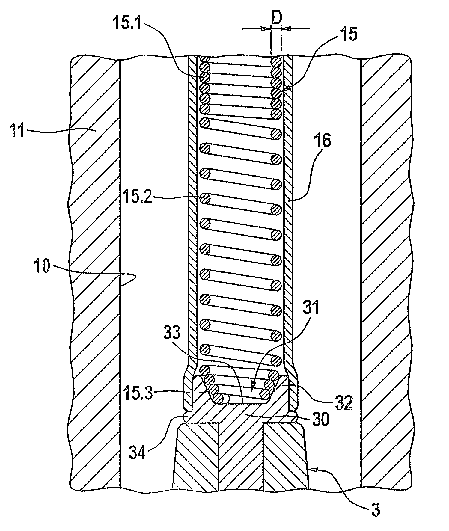
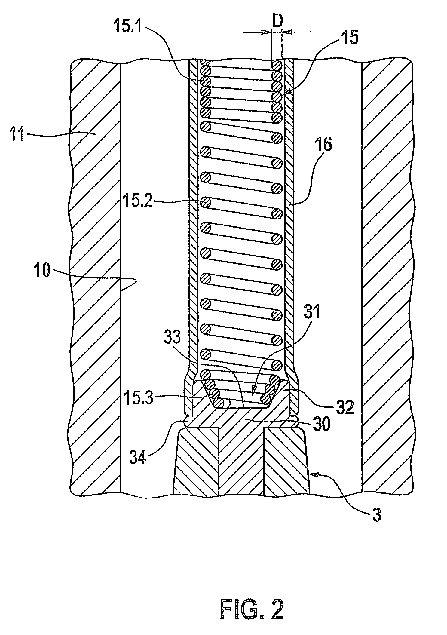
The present invention provides an ignition coil that allows for easy and reliable contact with a spark plug. This coil can be manufactured in a simple and cost-effective manner. It also ensures that a very small amount of space is needed at the contacting point with the spark plug, and it provides reliable shielding of the contact segment at the end of the spring of the ignition coil. The contact segment of the spring has a reduced outer diameter in comparison with the rest of the spring, which is shielded by a recess provided in the contact region of the spark plug. The reduced-circumference contact segment of the spring is tapered, which ensures effective centering and positioning during mounting, and it prevents wear and tear during vibrations. Additionally, the contact segment can have a frustoconical enveloping surface with an opening angle between 40-60 degrees, or it can be cylindrical with a smaller outer diameter than the rest of the spring.

Problems solved by technology

Such spark plugs have fundamentally proven their worth, but the spaces of modern engines are becoming more and more confined.
However, the sharp-edged end of the spring disadvantageously produces an increase in field strength between the end of the spring and the plug shaft.
Due to higher voltage requirements at this position, this may result in electrical breakdowns, which, however, must be absolutely avoided.

Method used


Image

  • Ignition coil, spark plug, and ignition set-up including an ignition coil and spark plug
  • Ignition coil, spark plug, and ignition set-up including an ignition coil and spark plug
  • Ignition coil, spark plug, and ignition set-up including an ignition coil and spark plug

Examples


Embodiment Construction

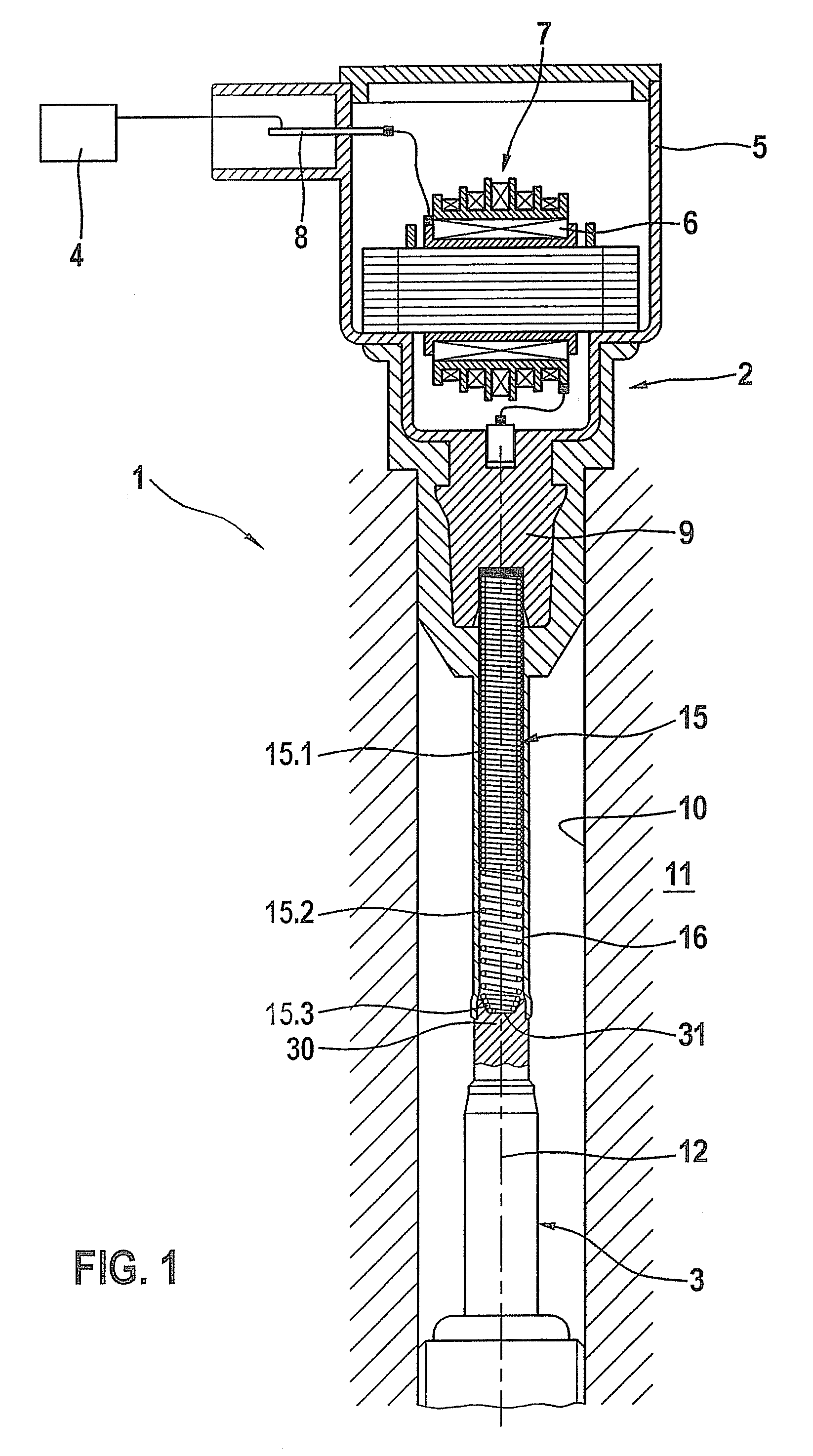
[0021]An ignition set-up 1 having an ignition coil 2 and a spark plug 3 according to a first exemplary embodiment of the present invention is described below with reference to FIGS. 1 through 3.

[0022]As is apparent from FIG. 1, ignition coil 2 includes a coil housing 5, in which a primary coil 6 and a secondary coil 7 interact in such a manner, that a high voltage for spark plug 3 is produced from a low d.c. voltage of a battery 4. Primary coil 6 is electrically connectable to battery 4 via a low-voltage terminal 8, and to spark plug 3 via a high-voltage terminal 9. Spark plug 3 is situated in a shaft 10 of a cylinder head 11 of an internal combustion engine. A center line of the spark plug and the ignition coil is designated by reference numeral 12.

[0023]As a contact element, ignition coil 2 further includes a spring 15 that is surrounded by an insulating protective sheath 16. In this context, the insulating protective sheath surrounds both high-voltage terminal 9 and a contact reg...


PUM

PropertyMeasurementUnit
opening angleaaaaaaaaaa

Abstract

In an ignition coil having a high-voltage terminal and a spring for electrically connecting the high-voltage terminal to a spark plug, a contact segment of the spring, which is directed towards the spark plug, has an outer circumference that is reduced in comparison with an outer circumference of further segments of the spring. The spark plug has a contact region for contacting with the spring of the ignition coil, which contact region has a recess surrounded by a closed, annular wall region for receiving the contact segment of the spring of the ignition coil.

Description

BACKGROUND OF THE INVENTION[0001]1. Field of the Invention[0002]The present invention relates to an ignition coil, a spark plug, as well as an ignition set-up including an ignition coil and a spark plug.[0003]2. Description of Related Art[0004]Various embodiments of ignition coils, spark plugs, as well as ignition set-ups made up of these are known from the related art. For example, published German patent application document DE 10 2007 026 669 A1 shows an ignition coil having a high-voltage terminal and a spring for electrically connecting the high-voltage terminal to a spark plug, where the spring is surrounded by a protective sheath. Thus, a contact between the spring and a contact region of the spark plug is formed in such a manner, that the spring has a conically widening contact segment, which is put over a contact region of the spark plug. Such spark plugs have fundamentally proven their worth, but the spaces of modern engines are becoming more and more confined. Thus, one o...

Claims


Application Information

Patent Timeline
Patent Type & Authority Patents(United States)
IPC IPC(8): H01T13/04H01T13/44H01T13/41H01F38/12H01T13/40F02P13/00H01R13/24F02P3/02
CPCF02P13/00H01F38/12H01T13/04H01T13/40H01T13/41H01T13/44F02D2400/22F02P3/02H01R13/2421
Inventor STEINBERGER, WERNER
Owner ROBERT BOSCH GMBH
Learn More