Energy recovery devices, systems, and methods

a technology of energy recovery device and energy recovery method, which is applied in the direction of domestic stoves or ranges, heating types, lighting and heating apparatus, etc., can solve the problems of attempting to capture and reuse waste heat, generating large amounts of heat and grease in restaurants, and wasting energy. , to achieve the effect of reasonable efficiency and efficient control of energy recovery

Active Publication Date: 2015-11-24
HALTON GROUP LTD
View PDF7 Cites 0 Cited by
  • Summary
  • Abstract
  • Description
  • Claims
  • Application Information

AI Technical Summary

Benefits of technology

[0007]Heat energy is recovered from a variety of sources and transferred to one or more consuming processes and / or converted to another usable form, such as electricity. The present systems are adapted for use in commercial kitchens, but can be used in other locations. Commercial kitchens may provide opportunities for usefully consuming waste energy. For example, hot water, low temperature heat can be used for hot water heating or pre-heating, food warming, absorbent-based air conditioning, dehumidification (e.g., desiccant regeneration) and other purposes. In addition, existing and new thermoelectric technologies permit thermal energy to be converted directly to electrical energy with reasonable efficiency.
[0024]The controller device may control the rate of heat recovery by allowing the circulating device to only circulate the heat-exchange fluid having a predetermined temperature from the arrangements of metal tubing to the location of heat utilization.
[0028]The plate-type thermoelectric conversion device may be incorporated in, positioned on, a movable sash that can be moved to a position that reduces the air flow aperture under the hood portion.

Problems solved by technology

Restaurants in general generate large amounts of heat and grease-laden exhaust from the frying and broiling of various food items which are prepared.
However, the heat is generally lost up the exhaust duct.
Any attempt to capture and reuse this waste heat runs into problems because energy recovery devices which use heat exchangers have either reduced heat-transfer properties due the grease that deposits on their surfaces, or because the heat extraction process employed to recover this heat is generally not very efficient.

Method used


Image

  • Energy recovery devices, systems, and methods
  • Energy recovery devices, systems, and methods
  • Energy recovery devices, systems, and methods

Examples


Embodiment Construction

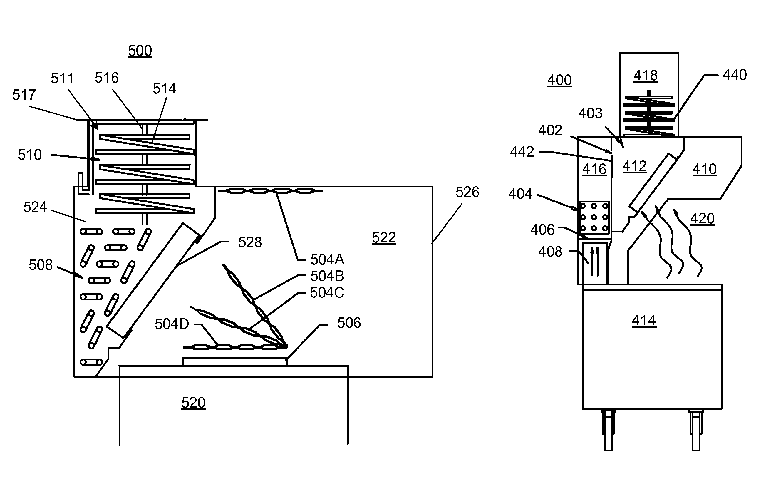
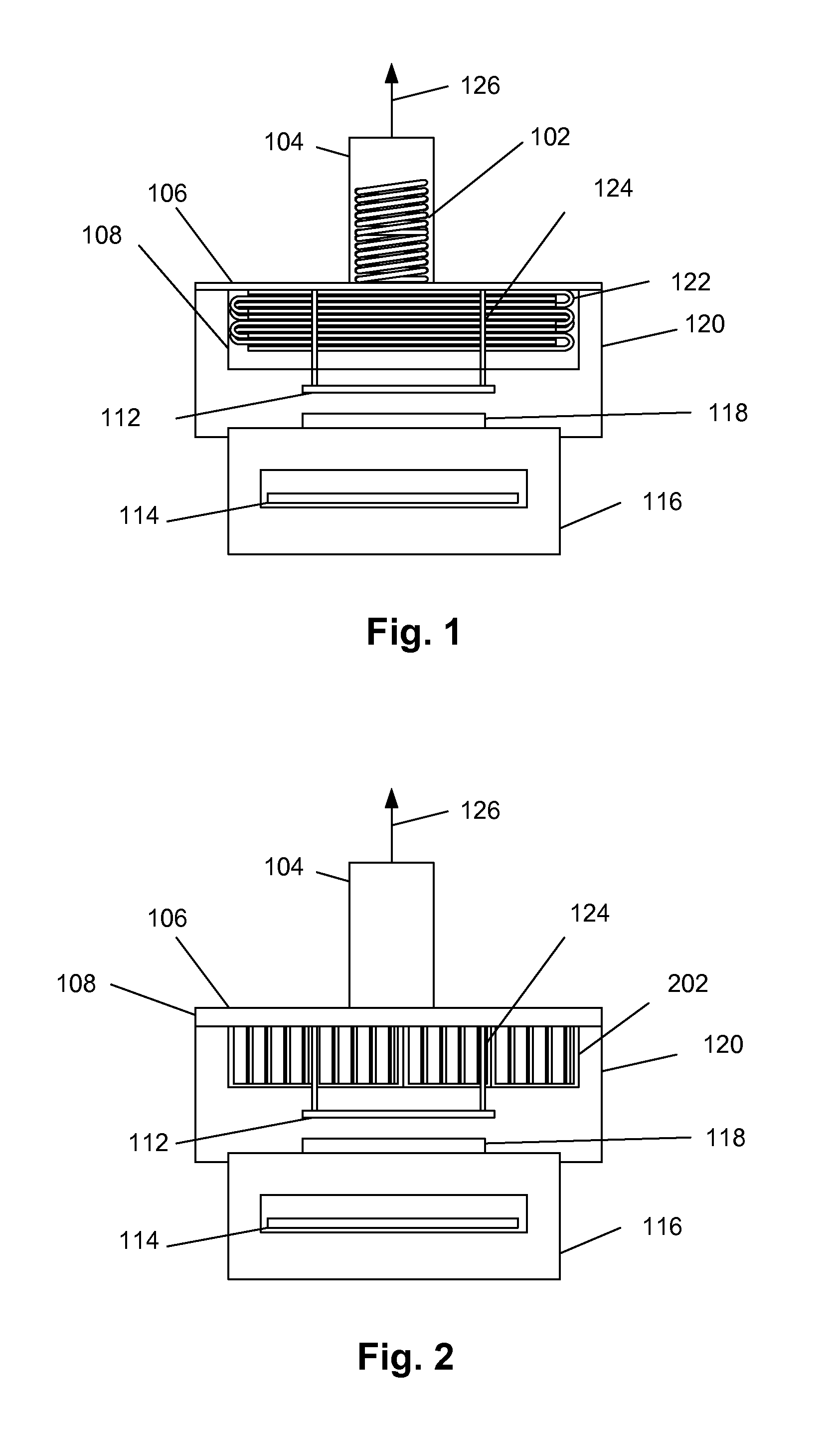
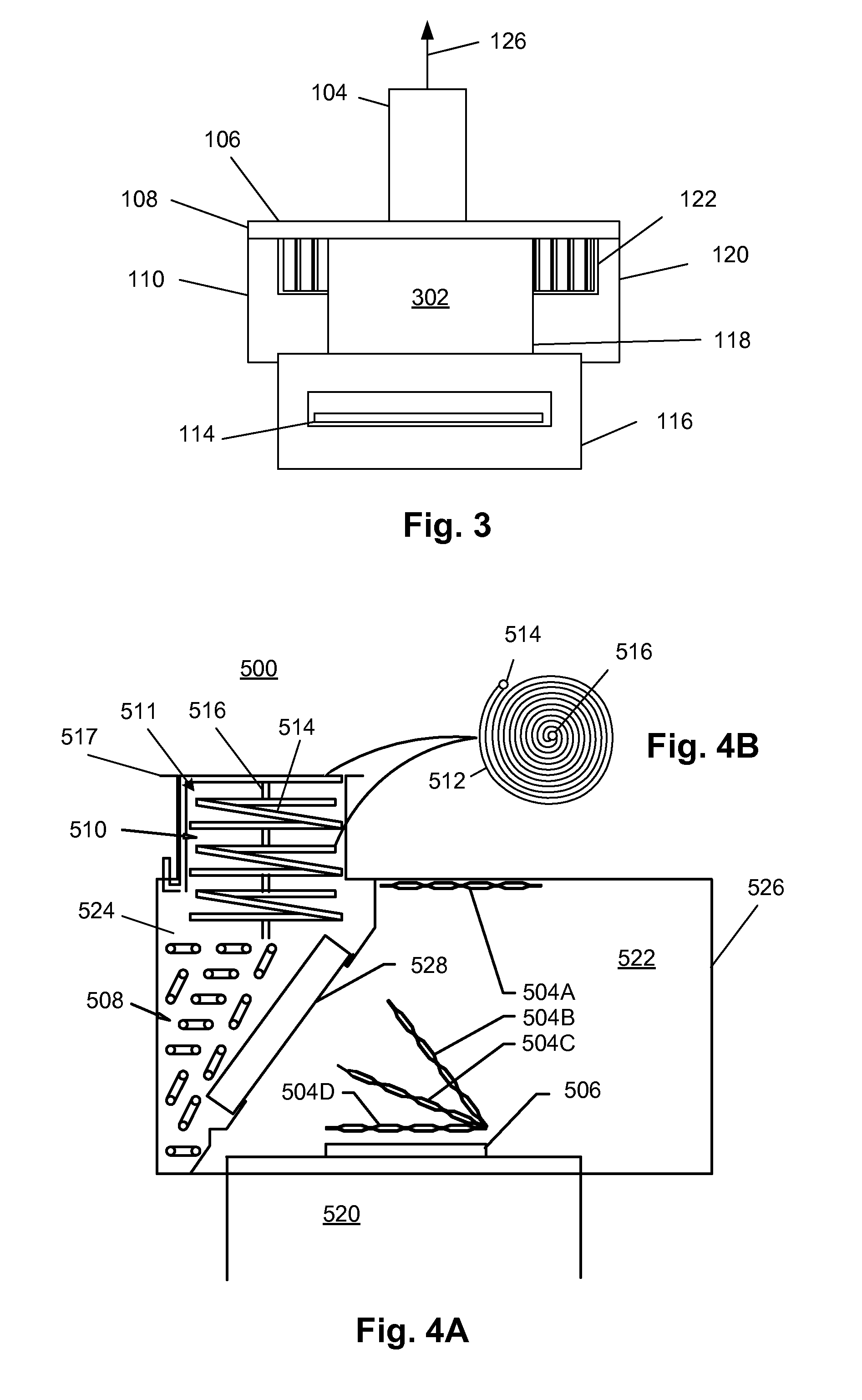
[0047]FIGS. 1 to 3 show an energy or heat recovery device for a grill 116. The chain broiler 116 receives food onto a grill configured as a conveyor belt 114 that passes food over a source of heat, such as a gas burner or wood fire. Radiant and convective heat and flue products emanate from an exhaust opening 118 at the top of the grill 116.

[0048]Fumes from the exhaust opening 118 are captured by an exhaust hood 120. Fumes are drawn by an exhaust fan into a plenum 108 through grease filters 202 and removed through an exhaust duct 104 and a cooled product 126 ultimately discharged.

[0049]A flat heat exchanger panel 112 is arranged to capture radiant energy and, under certain conditions (if the temperature is lower than the exhaust products) convective heat, emanating through the exhaust opening 118. A bent tube heat exchanger 122 is located in the exhaust plenum 108 and captures heat convectively. The grease filters 202 serve to reduce the amount of fouling experienced by the heat exc...


PUM


Abstract

Energy recovery devices, systems and methods, and energy recovery control systems and methods for efficient extraction and reuse of waste heat from exhaust fumes generated from cooking appliances.

Description

CROSS-REFERENCE TO RELATED APPLICATIONS[0001]The present application is a U.S. national stage entry of International Application No. PCT / US11 / 35599, filed May 6, 2011, which claims the benefit of U.S. Provisional Application No. 61 / 359,212, filed Jun. 28, 2010, and U.S. Provisional Application No. 61 / 332,176, filed May 6, 2010, all of which are hereby incorporated by reference herein in their entireties.RELATED FIELD[0002]The present invention relates generally to energy recovery devices, systems and methods and more particularly to energy recovery devices and energy recovery control systems and methods for efficient extraction and use of waste heat.BACKGROUND OF THE INVENTION[0003]Restaurants in general generate large amounts of heat and grease-laden exhaust from the frying and broiling of various food items which are prepared. This grease-laden hot exhaust is typically drawn up through a kitchen hood and exhaust duct combination to the atmosphere by a fan arrangement. However, the...

Claims


Application Information

Patent Timeline
Patent Type & Authority Patents(United States)
IPC IPC(8): F24C15/20
CPCF24C15/20F24C15/2042F24C15/2057F24C15/2021
Inventor PARVIN, FUOAD A.SCHROCK, DEREK W.LIVCHAK, ANDREY V.
Owner HALTON GROUP LTD
Why Eureka
Try Eureka