Antenna system for wireless terminal devices

a wireless terminal device and antenna technology, applied in the field of antenna systems, can solve the problems of reducing the gain of the antenna, affecting the performance of the active element, so as to improve the gain of the driven element, the effect of improving the gain

Active Publication Date: 2015-11-24
LENOVO PC INT
View PDF19 Cites 11 Cited by
  • Summary
  • Abstract
  • Description
  • Claims
  • Application Information

AI Technical Summary

Benefits of technology

[0011]In accordance with a preferred embodiment of the present invention, a mobile device includes an antenna system capable of providing an improved gain at around 700 Mhz. The mobile device includes a display casing with a conductive region and a non-conductive region. The antenna system includes a driven element having an inverted-F antenna arranged in the non-conductive region of the display casing. The display casing is also provided with an electrostatic discharge (ESD) conductor as a countermeasure against ESD. The ESD conductor is connected to the conductive region of the casing. The ESD conductor causes static charges in the air to be discharged to the conductive region of the casing. The ESD conductor also produces harmonic resonance and exchanges electromagnetic energy with the driven element to improve the gain of the driven element.

Problems solved by technology

Further, the antenna gain decreases when a sufficient element length cannot be secured for the resonance frequency.
Thus, a problem has arisen that, with the space conventionally available for the wireless WAN antenna, it would be difficult to guarantee sufficient gain for the frequencies near 700 MHz.
Meanwhile, a circuit board on which a camera and a microphone are mounted may be destroyed by a surge current that flows in from the outside through an opening of the display casing due to electrostatic discharge (ESD).
A conductor that is maintained at the ground potential existent in the vicinity of the antenna may adversely affect the radio properties of the antenna.

Method used


Image

  • Antenna system for wireless terminal devices
  • Antenna system for wireless terminal devices
  • Antenna system for wireless terminal devices

Examples


Embodiment Construction

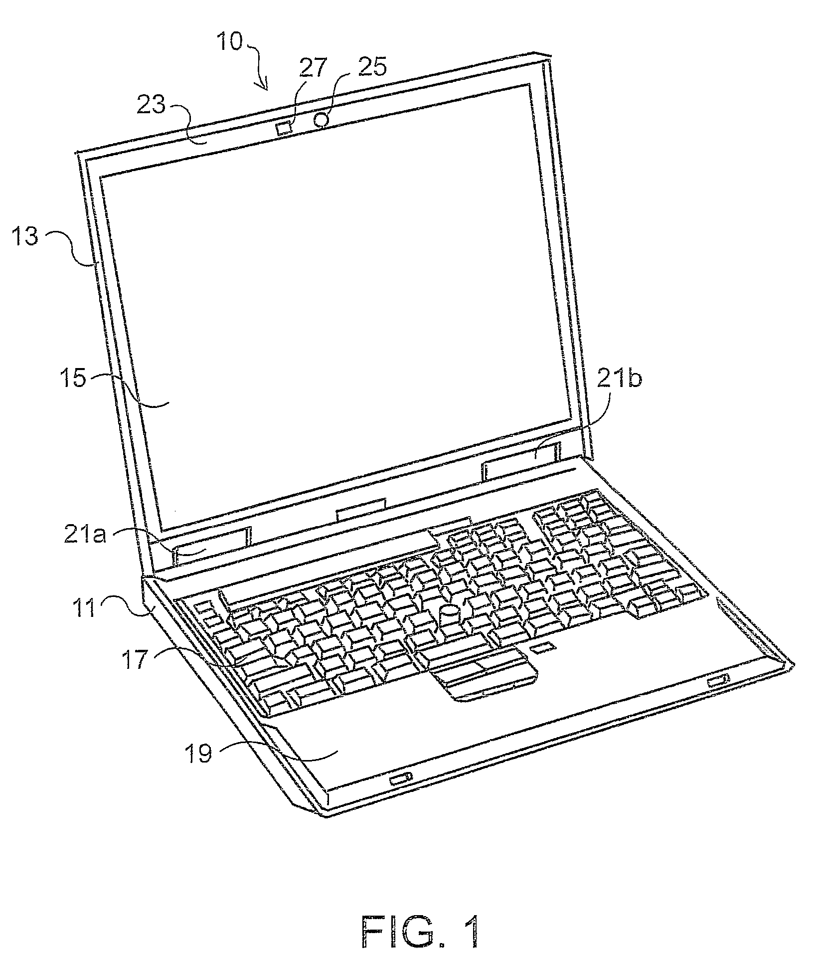
[0020]FIG. 1 is a perspective view of a laptop PC 10 according to a preferred embodiment of the present invention. The laptop PC 10 has an LCD module 15 housed in a display casing 13. A processor, a motherboard, a wireless module, a hard disk drive, and other system devices are housed in a system casing 11. A keyboard assembly 17 and a keyboard bezel 19 are attached to the upper surface of the system casing 11. The system casing 11 is made of a magnesium alloy. The system casing 11 and the display casing 13 are connected via hinges 21a and 21b in an openable and closable manner.

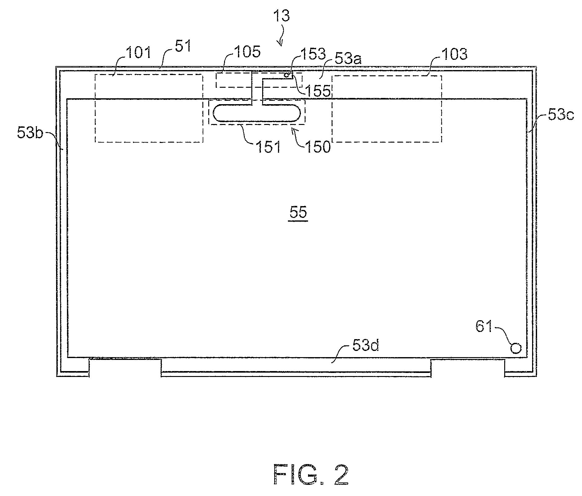
[0021]The display casing 13 is formed in a box shape to accommodate the LCD module 15 therein. A bezel 23 is attached to the display casing 13 to cover the gap formed between the side surface of the LCD module 15 and the inner surface of the sidewall of the display casing 13. Near the center of the bezel 23 on the upper side, an opening 25 for a camera and an opening 27 for a microphone are formed. The displa...


PUM


Abstract

An antenna system suitable for a mobile device is disclosed. The mobile device includes a display casing with a conductive region and a non-conductive region. The antenna system includes a driven element having an inverted-F antenna arranged in the non-conductive region of the display casing. The display casing is also provided with an electrostatic discharge (ESD) conductor as a countermeasure against ESD. The ESD conductor is connected to the conductive region of the casing. The ESD conductor causes static charges in the air to be discharged to the conductive region of the casing. The ESD conductor also produces harmonic resonance and exchanges electromagnetic energy with the driven element to improve the gain of the driven element.

Description

PRIORITY CLAIM[0001]The present application claims benefit of priority under 35 U.S.C. §§120, 365 to the previously filed Japanese Patent Application No. JP2012-027868 with a priority date of Feb. 11, 2012, which is incorporated by reference herein.BACKGROUND OF THE INVENTION[0002]1. Technical Field[0003]The present invention relates to antenna systems in general, and in particular to an antenna system adapted to a relatively low frequency band of wireless wide-area network.[0004]2. Description of Related Art[0005]A laptop personal computer (laptop PC) includes many antennas mounted thereon for handling different wireless communications systems such as WiMAX, wireless local-area network (wireless LAN), and wireless wide-area network (wireless WAN). A laptop PC performs data communication through the wireless WAN established by using a mobile phone communications network. In North America, primarily, the third generation (3G) personal communications service (PCS) band and the cellula...

Claims


Application Information

Patent Timeline
Patent Type & Authority Patents(United States)
IPC IPC(8): H01Q1/24H01Q1/00H01Q1/50H01Q1/52H01Q9/42H01Q1/22
CPCH01Q1/002H01Q1/2266H01Q1/241H01Q1/50H01Q1/526H01Q9/42
Inventor YAMAMOTO, OSAMUOKADA, TAKAAI
Owner LENOVO PC INT
Why Eureka
Try Eureka