Prestressed modular foam structures

a foam structure and prefabricated technology, applied in the field of prefabricated modular structures, can solve the problems of difficult manipulation and handling on the job site, tedious and cumbersome roof installation, and inability to achieve maximum practicable structural integrity with plastic foam panels or blocks alone, and achieve the effect of rapid connection

Inactive Publication Date: 2015-12-01
CONCRETE & FOAM STRUCTURES
View PDF91 Cites 9 Cited by
  • Summary
  • Abstract
  • Description
  • Claims
  • Application Information

AI Technical Summary

Benefits of technology

[0061]It is still another object of the present invention to provide a self-contained modular home which can be secured to a permanent foundation and be rapidly connected to water / sewer service and electrical service.
[0062]It is yet another object of the present invention to provide a self-contained modular home which can be set onto the foundation without the use of a crane.

Problems solved by technology

In some designs the roof is tedious and cumbersome to install.
Although some modules are bulky, their reduced weight eases the difficulty of manipulation and handling at the job site.
Another pertinent issue facing the designers or installers of modern, plastic block or panel structures involves the technique used for securing the blocks or panels together.
However, despite the above advancements associated with the use of modular foam building blocks or panels, many small, well known imperfections with such materials or components contribute to consumer apprehension and buyer resistance.
Furthermore, maximum practicable structural integrity cannot be achieved with plastic foam panels or blocks alone, despite their inherent strength.
Most importantly, the inherent thermal conductivity of metal reinforcement structures promotes thermal inefficiency or losses, so that such structures must be properly integrated within the foam construction modules to break or minimize loss-inducing, conductive heat paths.

Method used


Image

  • Prestressed modular foam structures
  • Prestressed modular foam structures
  • Prestressed modular foam structures

Examples


Embodiment Construction

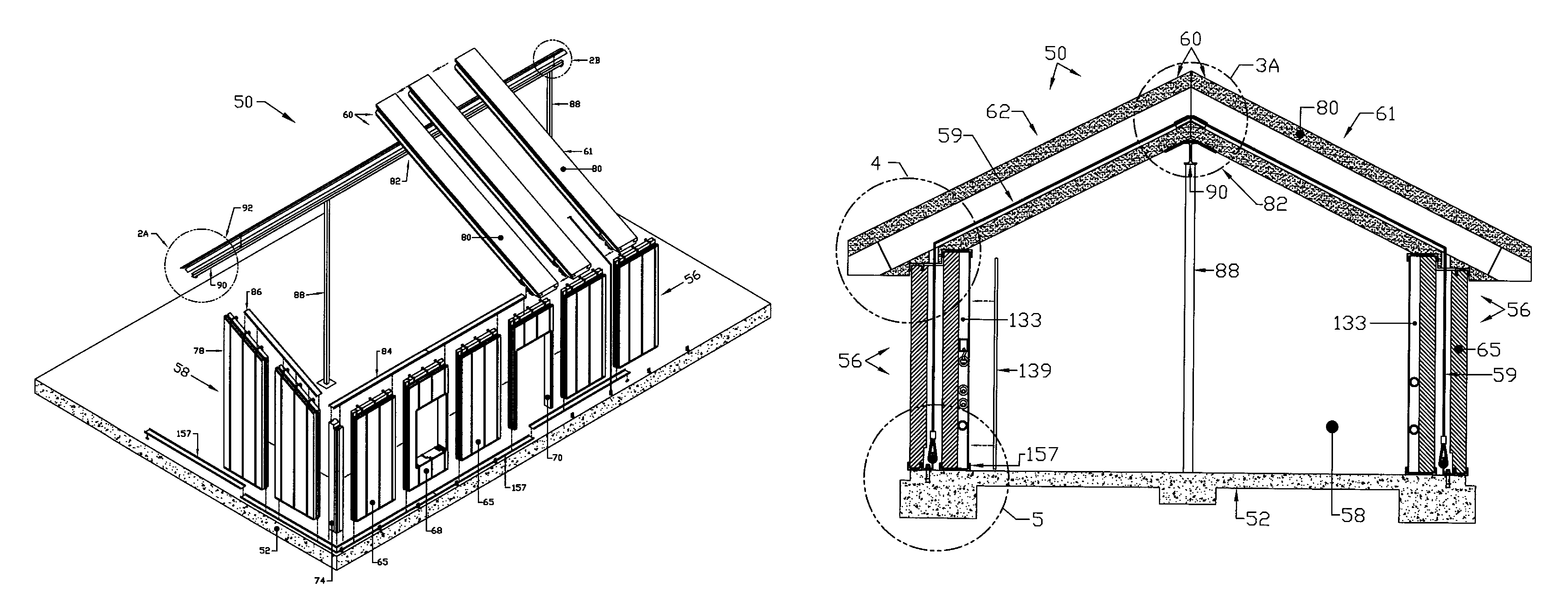
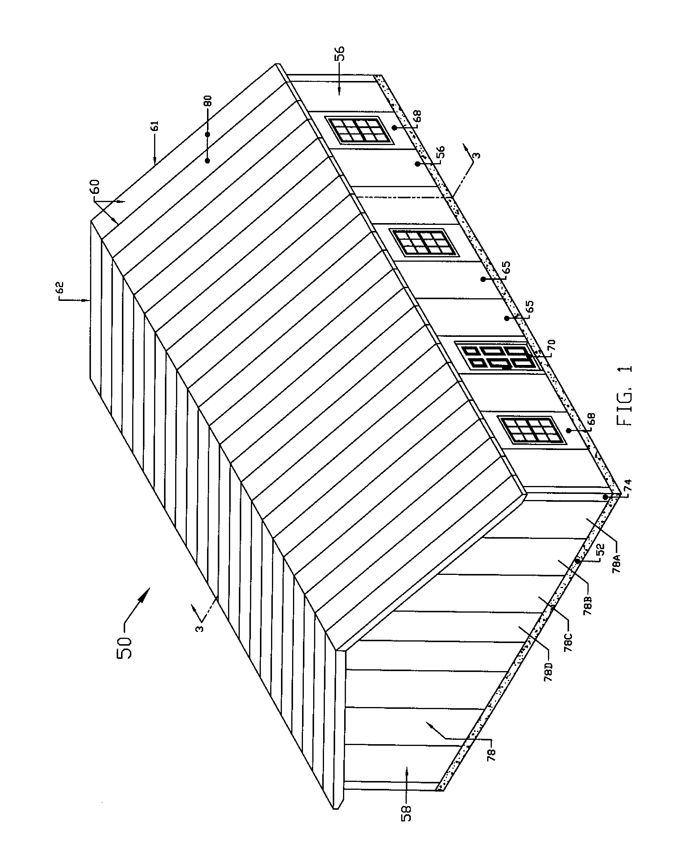
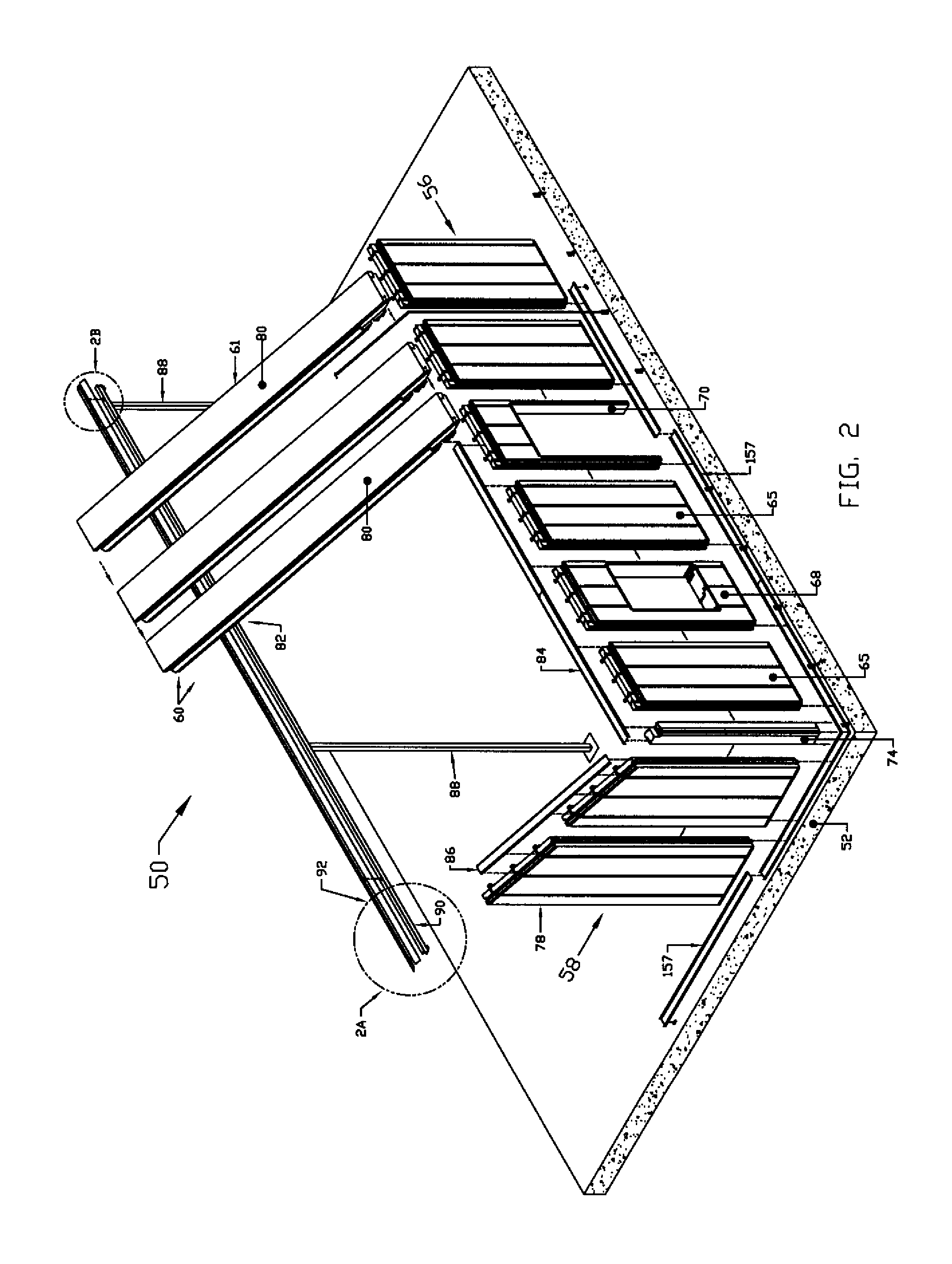
[0105]With initial reference now directed to FIGS. 1 and 2 of the drawings, an upright, energy-efficient, modular enclosure constructed in according to the best mode of the invention, has been generally designated by the reference numeral 50. Enclosure 50 is disposed upon and secured to a suitable supporting surface such as a conventional concrete slab 52. Alternatively the supporting surface may comprise a wooden floor, a pier and beam arrangement, or other horizontal, or elevated substantially rigid, supporting structure. The illustrated enclosure 50 is generally in the form of a house or dwelling, but the panels and modules of the invention may be formed into different building configurations with dissimilar dimensions, sizes and shapes with varying styles and character. Simply by varying the type, size and number of individual panels described below, diverse modules can be assembled at the job site and connected together to form custom walls, roofs, gable structures and the like...


PUM


Abstract

A prefabricated, modular enclosure comprising a plurality of plastic foam EPS components forming an integrated structure characterized by energy efficiency and ease of assembly. Wall panels, window panels, door panels, gable panels and roofing panels may be custom configured and glued together, utilizing adaptors on their sides and corner assemblies at intersections. The panels include major and minor channel struts that longitudinally penetrate the panel bodies, snugly lodging within receptive slots. The struts do not contact each other, and no portions of the struts traverses the panel thickness from inside to outside, thus minimizing thermal loss pathways. The wider, major reinforcement struts have offset portions spaced from interior panel surfaces that project interiorly of the enclosure and form a rigid mounting for interior finishing. The chase defined between the modular panels and the interior wall finishing, afforded by the offset struts, may house plumbing, wiring or the like.

Description

CROSS REFERENCE TO RELATED APPLICATION[0001]This utility patent application is based upon, and claims priority from, a previously filed U.S. Provisional Patent Application entitled “Prestressed Modular Foam Structures,” Ser. No. 61 / 762,394, filed in the U.S.P.T.O. Feb. 8, 2013, naming inventor John H. Bargh.BACKGROUND OF THE INVENTION[0002]I. Field of the Invention[0003]The present invention relates generally to prefabricated, modular structures. More particularly, the present invention relates to dwellings or enclosures that are assembled from modular components substantially comprised of foam plastic, which are fitted together, prestressed and secured upon suitable concrete slabs or foundations to form an enclosure or habitable dwelling, or the like.[0004]II. Description of the Prior Art[0005]It has long been recognized by those skilled in the art that substantial advantages are obtained with modular construction techniques and apparatus. Typically. the construction and assembly o...

Claims


Application Information

Patent Timeline
Patent Type & Authority Patents(United States)
IPC IPC(8): E04B7/06E04C5/12E04B7/02E04C5/08
CPCE04C5/08E04C5/12E04B7/026E04B7/06E04B7/22E04B1/14E04B2001/3583
Inventor BARGH, JOHN H
Owner CONCRETE & FOAM STRUCTURES
Why Eureka
Try Eureka