Medical device for electrical stimulation

a medical device and electrical stimulation technology, applied in the field of medical devices for electrical stimulation, can solve the problems of difficult to make long wound structures using thin-film technology, unfavorable dc resistance increase, and damage to brain tissue that can have very severe consequences, so as to reduce the risk of injury, alleviate the effect or eliminate the injury

Active Publication Date: 2015-12-08
MEDTRONIC BAKKEN RES CENT
View PDF25 Cites 1 Cited by
  • Summary
  • Abstract
  • Description
  • Claims
  • Application Information

AI Technical Summary

Benefits of technology

[0008]It would be advantageous to achieve an implantable device which is compatible with MRI. To this end, it would be advantageous to achieve an implantable device comprising conductive parts, which minimizes or which renders low any associated temperature rises in the conductive parts during exposure to rapidly changing electromagnetic fields. In general, the invention preferably seeks to mitigate, alleviate or eliminate one or more of the above mentioned disadvantages singly or in any combination. In particular, it may be seen as an object of the present invention to provide a method that solves the above mentioned problems, or other problems, of the prior art.
[0010]By winding the one or more electrical conductors, generally the impedance of the probes can be increased at high frequencies (MRI frequencies) due to self-inductance from the windings while the DC resistance at low frequencies (stimulation frequencies) can be kept sufficiently low to ensure long battery life of an associated battery-powered pulse generator. MRI frequencies are typically between 42 MHz for 1-Tesla systems to 128 MHz for 3-Tesla systems; and typically neurostimulation-stimulation pulses contain frequencies in the range from 0.001 to 10 kHz. The inventors of the present invention have realized that quite a large number of windings may be needed in order to suppress sufficiently the impedance at MRI frequencies. Thus the length of the electrical connectors needed in connection with wound conductors can be quite large. The electrical connectors may be fabricated in different ways. In one way, the electrical connectors are fabricated using thin-film technologies. Long wound structures may be difficult to make using thin-film technology. Moreover, as the length of the wires increases also the DC resistance increases which is undesirable in connection with battery life requirements. The inventors of the present invention have further realized that heating resulting from MRI scanning with an implanted medical device is non-uniformly distributed along the device. Thus by configuring the windings of the electrical conductors, such that the density of windings is non-uniformly distributed along the length axis, a high density of windings can be used in areas where this is needed, whereas a lower density of windings can be used in areas where problems related to heating are less severe. Since the same high density of windings is not used along the entire wound areas, the number of windings and thus the length of the electrical conductors are reduced, and at the same time, from the presence of the windings, the impedance can be increased sufficiently at appropriate areas to render the device suitable for use in connection with implantation and MRI.
[0013]It is an advantage of embodiments of the present invention that different specific configurations of the windings can be used to provide various devices which can be tailored to specific situations of use. Example embodiments comprise that the one or more electrical conductors are wound along substantially the entire length of the conductor and that the one or more electrical conductors are wound in one or more discrete sections separated by non-wound sections.

Problems solved by technology

Long wound structures may be difficult to make using thin-film technology.
Moreover, as the length of the wires increases also the DC resistance increases which is undesirable in connection with battery life requirements.
In particular, the device may be beneficially applied in connection with deep brain simulation (DBS), since brain tissue is particularly sensitive to local heating, and moreover any damage of the brain tissue can have very severe consequences.

Method used


Image

  • Medical device for electrical stimulation
  • Medical device for electrical stimulation
  • Medical device for electrical stimulation

Examples


Embodiment Construction

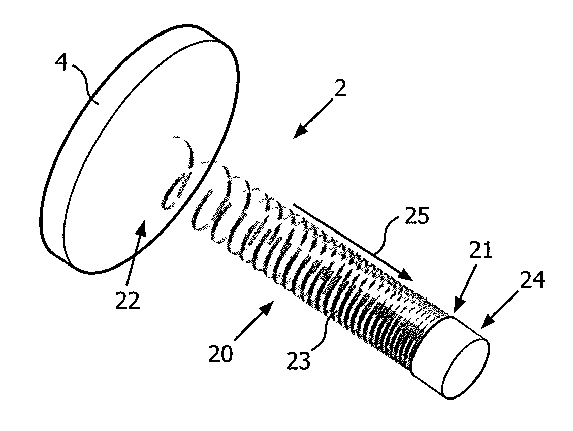
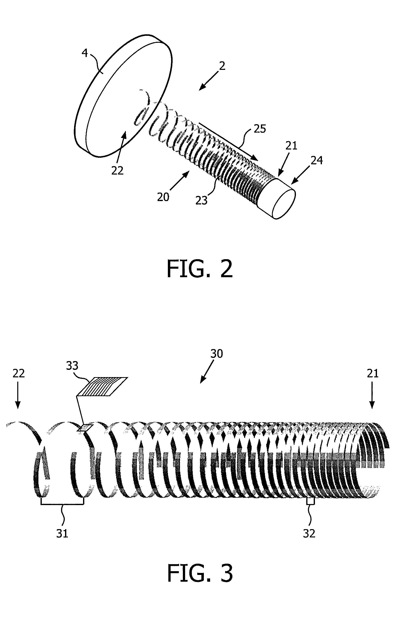
[0025]In this section, the present invention is primarily disclosed in connection with a medical device for electrical stimulation in the form of a device for deep brain stimulation (DBS). While, the DBS-device is an important application of the device in accordance with embodiments of the present invention, the device may be applied in connection with a large number of applications where a metal wire is used for electrical stimulation or sensing of a body part.

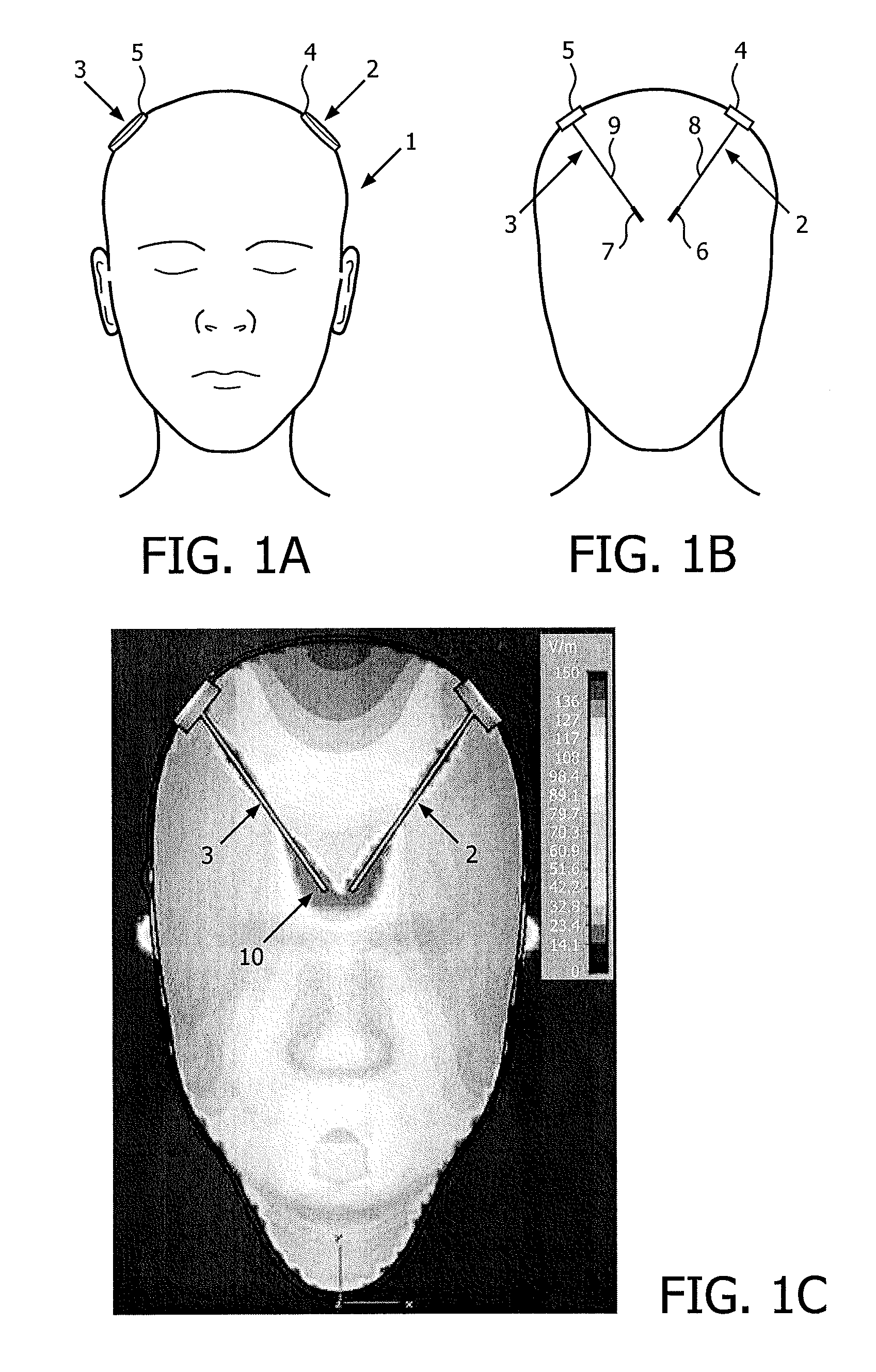
[0026]FIGS. 1A and 1B schematically illustrate DBS devices (also referred to as DBS probes) positioned in the head of a person. FIG. 1A schematically illustrates a person 1 having two DBS probes 2, 3 partly implanted in the head for stimulation of the left and the right side of the brain, whereas FIG. 1B illustrates a schematic cross-sectional view of the person shown on FIG. 1A. The placement and number of the DBS probes(s) is determined in accordance with the type of symptoms to be addressed. The shown example is merely for...


PUM


Abstract

The present invention relates to a medical device (2) for electrical stimulation. The device comprising an implantable elongated lead system (20) having a distal end (21) and a proximal end (22), the lead system comprises one or more electrical conductors (23) for connection to one or more electrodes (24). The one or more electrical conductors are wound along a length axis (25) of the lead system with a plurality of windings, and wherein the density of windings is non-uniformly distributed along the length axis. In an embodiment, the medical device is in the form of a deep brain stimulation (DBS) device.

Description

CROSS-REFERENCE TO RELATED APPLICATIONS[0001]This application is a National Stage Patent Application of International Patent Application No. PCT / IB2010 / 053250 filed on Jul. 16, 2010, which claims priority to United States Provisional Patent Application 61 / 228,231 filed on Jul. 24, 2009, both of which are incorporated herein by reference in their entirety.FIELD OF THE INVENTION[0002]The present invention relates to a medical device for electrical stimulation. In particular the invention relates to such a device comprising implantable parts.BACKGROUND OF THE INVENTION[0003]Electrical stimulation therapy is a fast-growing field, largely related to the successful use of implantable electrical stimulation devices for a wide range of applications. One important application is Deep Brain Stimulation (DBS). The DBS system may comprise two components: an implanted pulse generator (IPG) and a probe. The IPG is a battery powered neurostimulator that sends electrical pulses to the brain to inte...

Claims


Application Information

Patent Timeline
Patent Type & Authority Patents(United States)
IPC IPC(8): A61N1/05A61N1/00A61N1/08A61N1/36
CPCA61N1/00A61N1/0534A61N1/36082A61N2001/086A61N1/086A61N1/36125
Inventor HARBERTS, DIRK WILLEMVETTER, RIO
Owner MEDTRONIC BAKKEN RES CENT
Why Eureka
Try Eureka