Vehicle wheel rim

a technology for wheels and rims, applied in the direction of spoked wheels, transportation and packaging, rolling resistance optimization, etc., can solve the problem of reducing the overall radial rigidity of the rim assembly

Inactive Publication Date: 2015-12-22
SCHLANGER RAPHAEL
View PDF16 Cites 2 Cited by
  • Summary
  • Abstract
  • Description
  • Claims
  • Application Information

AI Technical Summary

Benefits of technology

[0007]This separable / joinable apex region design provides several advantages. Firstly, the rim assembly may be made to include two rim shell portions that may each be separately formed and then assembled back-to-back in a clamshell design. This split design greatly simplifies the molding and / or processing involved to form the parts as they may now be molded with a simple axial draw between mold halves, which reduces processing cost. This also means that the clamshell portions may be produced from simple sheet material of generally uniform thickness, which is generally very economical. Further, the amount of manual labor required for molding is greatly reduced in comparison with prior art designs. It is envisioned that these rim shells may be produced in a vacuum-forming and / or pressure-forming process, indeed a very economical process that would be impossible with prior art rim designs.
[0008]Further, since only the outer rim portion is now required to support the spoke connections, the rim shells may be made of very lightweight material, which results in a completed rim assembly that may be lighter in weight than prior art designs. Still further, the rim shells provide the aerodynamic and aesthetic benefits that customers are looking for. Yet further, since the rim shells do not support the spoke connections, they may be allowed to flex slightly, which reduced the overall radial rigidity of the rim assembly, for greater rider comfort and stability than prior art rim designs.
[0009]Also, this split design permits a seam that may be separated to provide access to the interior cavity of the rim assembly. This means that there is a wide range of alternate spoke connection designs that may be utilized with the present invention, which will provide enhanced performance and strength of the completed wheel assembly. Furthermore, with access to the interior cavity of the rim assembly, the rim cavity may be used to shield and enclose enlarged portions of the spoke(s), which further aids in aerodynamics and also adds to the available flexibility of the spoke design. Additionally, the interior access afforded by this split design provides easier assembly and lacing and also easier service in the field.
[0010]The present invention provides a wide range of options in the openings utilized to allow the spokes to pierce through the rim shell. The rim shell may be slotted to allow for passage of the spoke. This allows the rim shell to be assembled after the spoke is connected to the outer rim. It also allows the rim shell to be separated while the spokes remain connected to the outer rim. This provides tremendous design flexibility and ease of assembly and service that is not possible with prior art rim designs.

Problems solved by technology

Yet further, since the rim shells do not support the spoke connections, they may be allowed to flex slightly, which reduced the overall radial rigidity of the rim assembly, for greater rider comfort and stability than prior art rim designs.

Method used


Image

  • Vehicle wheel rim
  • Vehicle wheel rim
  • Vehicle wheel rim

Examples


Embodiment Construction

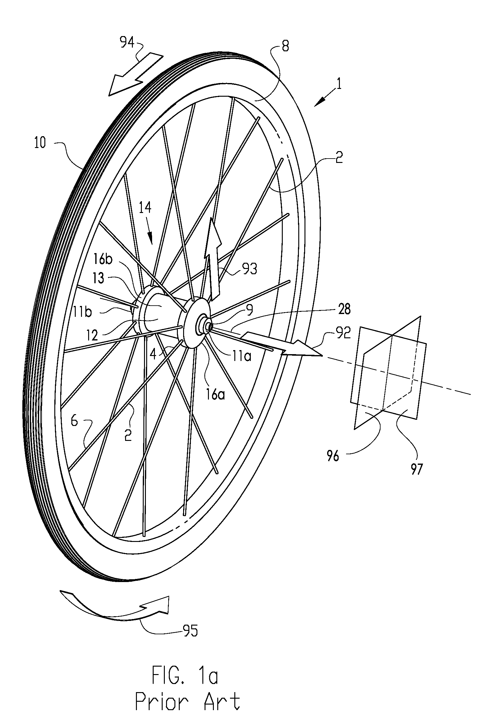
[0036]FIG. 1a describes the basic configuration of an exemplary vehicle wheel, in particular, a bicycle wheel 1, as well as a description of the direction conventions used throughout this disclosure. The hub shell 14 is rotatable about the axle 9 and includes at least two axially spaced hub flanges 16a and 16b (as shown in FIG. 2a), each of which include a means for connecting with the spokes 2. The hub flanges 16a and 16b may be contiguous with the hub shell 14 or they may be separately formed and assembled to the hub body 12 portion of the hub shell 14. The spokes 2 are affixed to their respective hub flanges 16a and 16b at their first end 4 and extend to attach the rim 8 at their second end 6. The tire 10 is fitted to the outer periphery of the rim 8. The wheel of FIG. 1a is generic and may be of tension-spoke or compression-spoke design.

[0037]The axial direction 92 is a direction parallel with the axial axis 28. The radial direction 93 is a direction generally perpendicular to t...


PUM


Abstract

A vehicle wheel, including: a peripheral rim with a radially outboard spoke bed and an apex region radially inboard from the spoke bed portion; a central hub with a hub flange; and a plurality of spokes extending between the rim and hub, with a first portion connected to the spoke bed and a second portion connected to the hub flange. The apex region includes a first apex portion and a second apex portion adjacent the first apex portion and a seam between the first apex portion and the second apex portion. Including a spanning element to span across said seam to retain said first apex portion to said second apex portion.

Description

CROSS-REFERENCE TO RELATED APPLICATION[0001]This application claims priority of U.S. patent application Ser. No. 12 / 661,154, filed Mar. 11, 2010, and entitled “VEHICLE WHEEL RIM”, which claims priority of U.S. provisional patent application 61 / 209,813, filed Mar. 12, 2009, and entitled “VEHICLE WHEEL RIM”.BACKGROUND OF THE INVENTIONDescription of Prior Art[0002]In the design of high performance bicycle wheels, in addition to strength, stiffness and durability, it is an object to make the wheels as aerodynamic and as aesthetically pleasing as possible. This usually involves increasing the depth of the rim cross section. these “deep-section” rims provide greatly improved aerodynamics in comparison with more conventional shallow-section rimmed wheels. In the past decade, these deep-section wheels have become commonplace. These rims are usually produced simply as elongated conventional rims, where the spokes are fastened to the rim at the spoke bed at the radially inboard apex of the ri...

Claims


Application Information

Patent Timeline
Patent Type & Authority Patents(United States)
IPC IPC(8): B60B7/01B60B7/06B60B7/04B60B1/00B60B21/02B60B21/04B60B25/00
CPCB60B7/01B60B1/003B60B7/06B60B7/063B60B21/025B60B25/00B60B21/04B60B2900/1216B60B7/04B60B2310/218B60B2900/111B60B2900/113Y02T10/86Y02T10/88
Inventor SCHLANGER, RAPHAEL
Owner SCHLANGER RAPHAEL
Why Eureka
Try Eureka