System with magnetically stable states and method for asserting magnetically stable state

a magnetic stable state and state technology, applied in the field of magnetic stable state system and method for asserting magnetic stable state, can solve the problems of slow magnetic hd, inability to achieve solid state hd, and inability to achieve data density limits,

Inactive Publication Date: 2015-12-29
CITY UNIVERSITY OF HONG KONG
View PDF23 Cites 1 Cited by
  • Summary
  • Abstract
  • Description
  • Claims
  • Application Information

AI Technical Summary

Problems solved by technology

This sophisticated level of mechanics results in at least three unfortunate consequences.
In particular, a magnetic HD is slow, energy consuming, and quite delicate, the last two limitations being largely unacceptable in portable devices.
However, after only a few years from their initial commercialization, such solid state HDs already appear to have reached a data density limit, despite the fact that the memory capacities remain about one order of magnitude smaller than that of a standard magnetic HD.
In principle, this data density limit of FLASH memory technologies is the same as that limiting the performance of the very fast DRAMs.
However, in all these cases, density is limited by electromagnetic cross-talk effects, when the writing process relies on the local magnetic field produced by the current flowing on the address lines (Nozaki et al.
U.S. Pat. No. 7,106,624 (B2)) but, so far, this requires large current densities, with a consequent limitation of the bit density due to Joule heating.
Accordingly, a challenge remains in the field of magnetic bit cells to find scalable magnetic structures that can be switched between two stable magnetic configurations while using small write currents.

Method used


Image

  • System with magnetically stable states and method for asserting magnetically stable state
  • System with magnetically stable states and method for asserting magnetically stable state
  • System with magnetically stable states and method for asserting magnetically stable state

Examples


Embodiment Construction

[0028]One or more embodiments are now described with reference to the drawings, wherein like reference numerals are used to refer to like elements throughout. In the following description, for purposes of explanation, numerous specific details are set forth in order to provide a thorough understanding of the various embodiments. It may be evident, however, that the claimed subject matter may be practiced without these specific details. In other instances, well-known structures and devices are shown in block diagram form in order to facilitate describing the various embodiments.

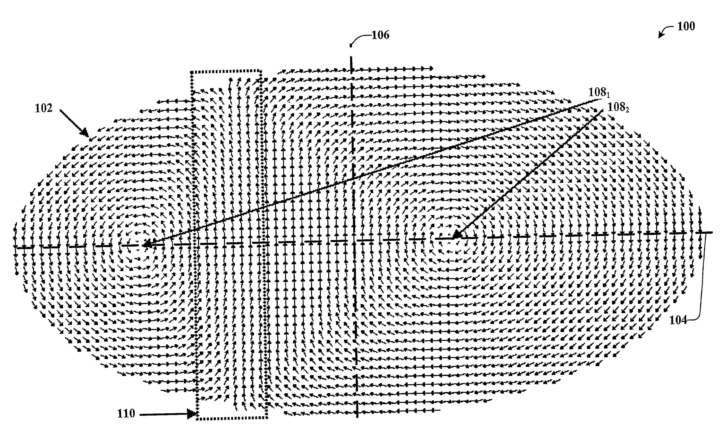
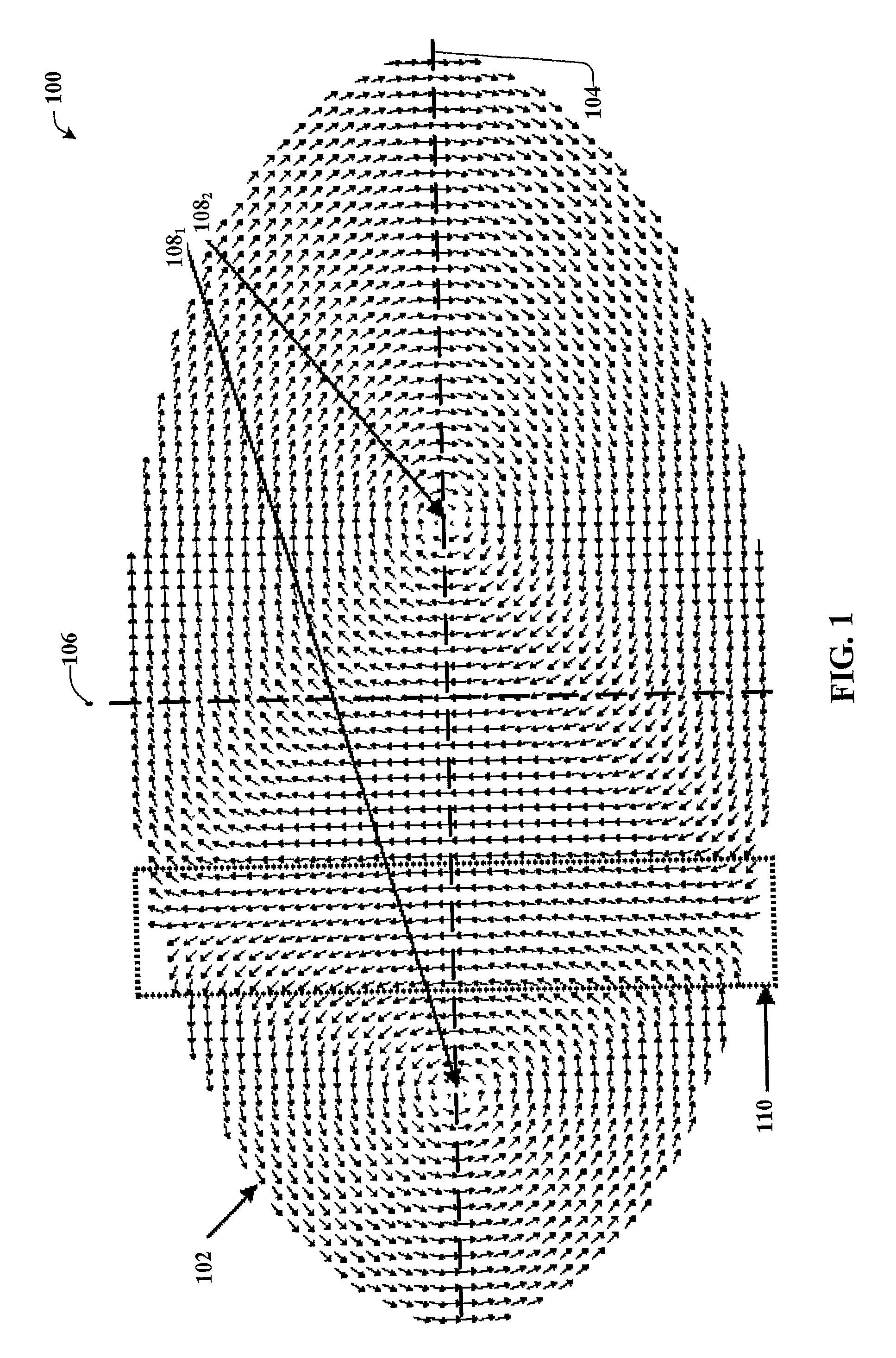
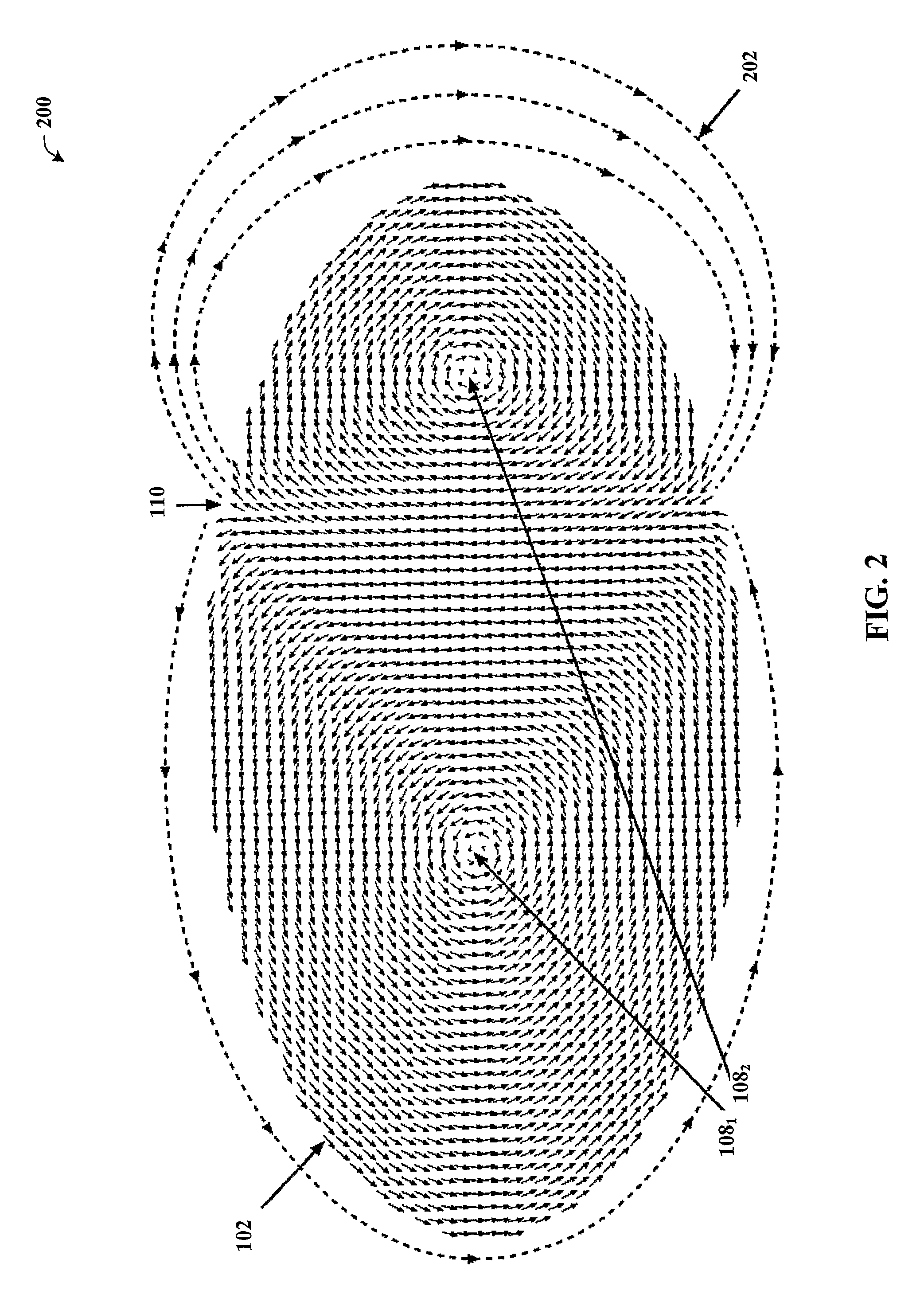
[0029]What is disclosed herein generally relates to a magnetic, conductive bit cell or components thereof that can be switched between two stable, specular magnetic configurations by the application of a small current perpendicular to the bit cell plane. The cell can consist of an elongated magnetic element or “dot,” the geometry of which is chosen so as a non-uniform magnetic configuration, consisting of two ...


PUM


Abstract

The disclosed subject matter relates to a non-volatile memory bit cell (500 or 600) for solid-state data storage, including, e.g., an elongated magnetic element (102) or “dot”. For appropriate geometry and dimensions of the dot, a two-fold, energetically-degenerate micromagnetic configuration (100 or 200) can be stabilized. Such a stable configuration can consist of two magnetic vortices (1081, 1082) and a flower state region (110). Due to energy minimization, the flower state region can be off-center (relative to a minor axis (106)) and along the major axis (104) of the dot. An electrical current (302) flowing perpendicular to the plane at, or in proximity to, the dot center can, according to current polarity, switch the configuration or state of the dot between the two specular magnetically stable configurations (e.g., a write operation). Reading of the cell state can be accomplished by using the magnetoresistive effect.

Description

CROSS-REFERENCE TO RELATED APPLICATION[0001]The subject application is a US national stage application of PCT Application Serial No. PCT / CN2010 / 001323, filed Aug. 31, 2010, and entitled “MAGNETIC MEMORY CELL,” the disclosure of which is incorporated herein by reference in its entirety.BACKGROUND OF THE INVENTION[0002]Virtually every computer, appliance, or portable device makes use of mainly three different memory technologies to store and retrieve information: (1) a magnetic hard disk (HD), (2) dynamic random access memory (DRAM), and / or (3) FLASH memory technologies. The combined use of as many as three different technologies is generally due to the need to overcome various limitations exhibited by each individual technology.[0003]For example, magnetic HDs provide the largest possible data density, yet magnetic HDs make use of sophisticated mechanics to enable such high data density. This sophisticated level of mechanics results in at least three unfortunate consequences. In parti...

Claims


Application Information

Patent Timeline
Patent Type & Authority Patents(United States)
IPC IPC(8): G11C11/16H01L43/08G11C11/14G11C11/02G11C11/18H01L27/22
CPCH01L43/08G11C11/02G11C11/14H01L27/228G11C11/18H01L27/222G11C11/16G11C11/161G11C11/1673G11C11/1675G11C11/1693H10B61/00H10B61/22H10N50/10
Inventor RUOTOLO, ANTONIO
Owner CITY UNIVERSITY OF HONG KONG
Why Eureka
Try Eureka