
Low profile battery module and improved thermal interface

a battery module and low-profile technology, applied in the field of low-profile battery modules, can solve the problems of increasing the scope and complexity of fraction battery packs, imposing certain design constraints on the modules, and affecting the quality of the battery pack, so as to achieve low parts count, good thermal characteristics, and low cost. the effect of low parts coun

Active Publication Date: 2015-12-29
KLEENSPEED TECH
View PDF1 Cites 21 Cited by
  • Summary
  • Abstract
  • Description
  • Claims
  • Application Information

AI Technical Summary

Benefits of technology

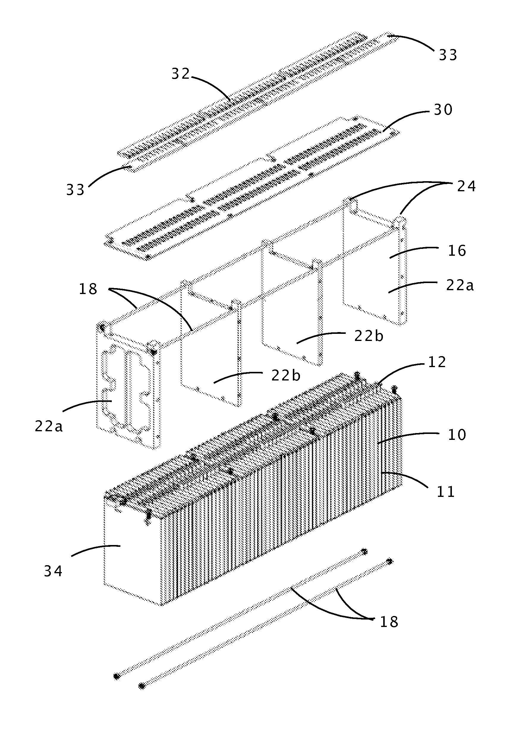
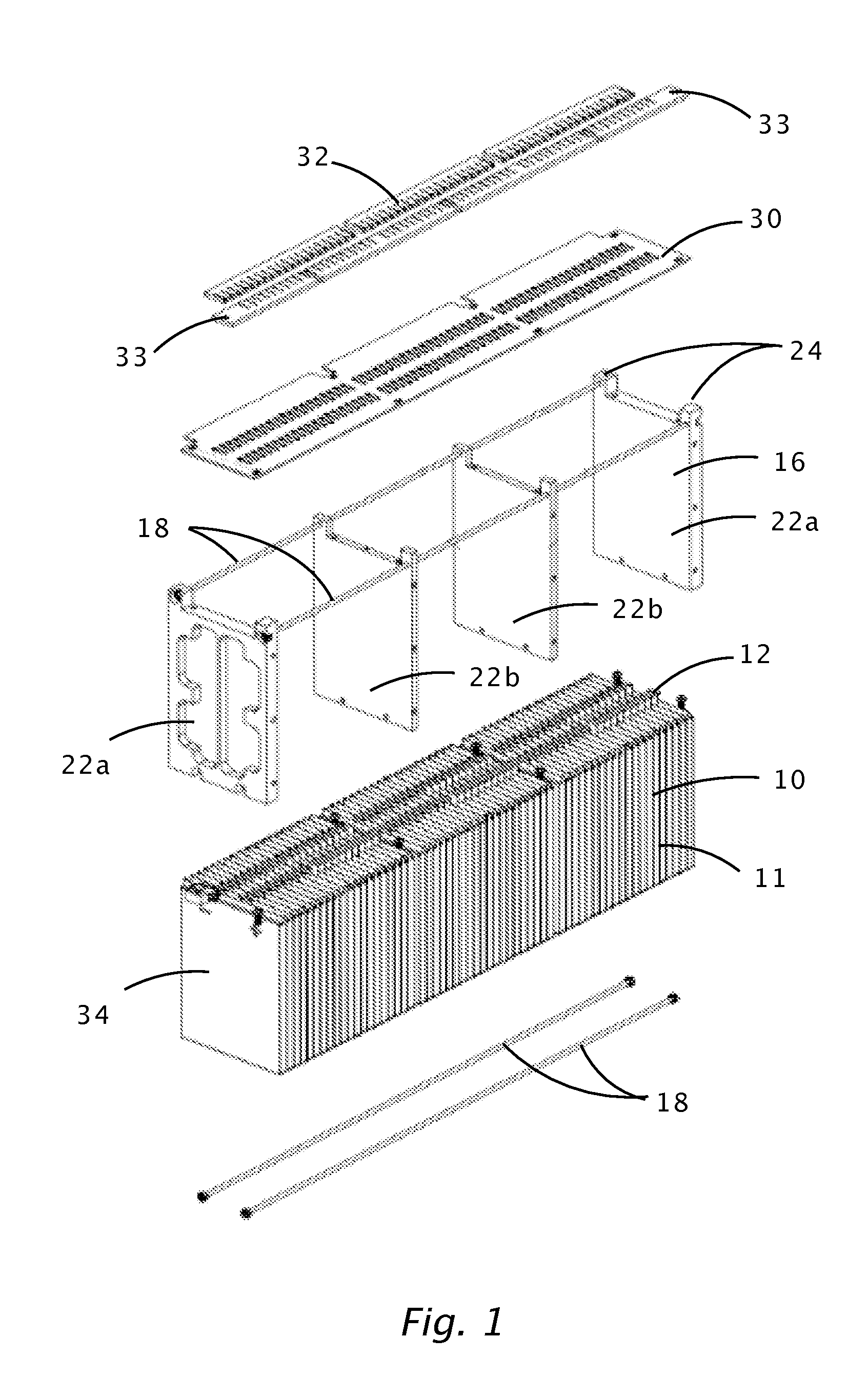
The patent describes a battery module that uses a special clamping system and epoxy material to keep the cells in place and prevent them from swelling. This design also allows for easy integration with heat collection manifolds or chill plates, and a low thermal resistance path from the cells to the external surfaces. The module also includes an insulating panel that holds the cell terminals in position and acts as a support structure for attaching the battery tabs to the bus bars. Overall, this design is compact, easy to manufacture, and has good thermal characteristics with a low parts count.

Problems solved by technology

With the trend toward higher pack voltages and the use of Lithium-based batteries, the scope and complexity of fraction battery packs has increased.
A practical height of such a battery pack from the top to the bottom of the enclosure is approximately 15 centimeters, and this height restriction imposes certain design constraints on the modules.
Pouch type cells are relatively flexible and vulnerable to impact and abrasion, and assembling large numbers of these cells into a rigid module can be difficult.
Thermal management of pouch cells can also be difficult.
When pouch cells are stacked together, the sides of the assembly are usually flexible and uneven, making it difficult to interface the assembly with a thermal management system.
Degradation of a single connection can lead to battery pack failure with potentially dangerous results such as fire.
Prior art battery modules may not satisfy the requirements for traction battery modules.

Method used


Image

  • Low profile battery module and improved thermal interface
  • Low profile battery module and improved thermal interface
  • Low profile battery module and improved thermal interface

Examples


second embodiment

[0050]FIG. 4 is a simplified representation of a battery pack 50 comprised of a plurality of battery modules 40. The battery modules illustrated are of a second embodiment having reinforcing side panels 41. The battery pack enclosure includes a bottom 52 and a top 54, and the bottom has reinforcing features 53.

[0051]In the figure, the battery modules are shown staggered to better distinguish the individual modules. It can be seen that the battery modules of the current invention, having a low profile prismatic shape, can be easily arranged to form a battery pack. This arrangement is highly scalable and uses short interconnections. In a small automobile, the battery modules can be arranged in two adjacent rows comprising approximately 16 to 18 modules. The resulting pack voltage is approximately 355 to 400 Volts.

[0052]FIG. 5 shows a typical application in which the battery pack 50 is integrated into an electric vehicle 56. This arrangement can be seen to result in a low center of gra...

first embodiment

[0054]Another benefit of this series-parallel arrangement is that the failure of a single cell is not catastrophic. In the first embodiment incorporating 10 cells per group, a cell failure only reduces energy capacity by 10%, as opposed to a series string, where a single cell failure can disable the entire pack.

[0055]FIG. 7 shows an embodiment of the slotted panel in which the panel is a printed circuit board 44. The figure identifies possible locations of some BMS components 60. The slotted holes 62 are used to attach the PC board to the lateral plates (not shown). The slotted holes 62 permit adjustment of the lateral plates in the long direction to accommodate variations in unit cell thickness.

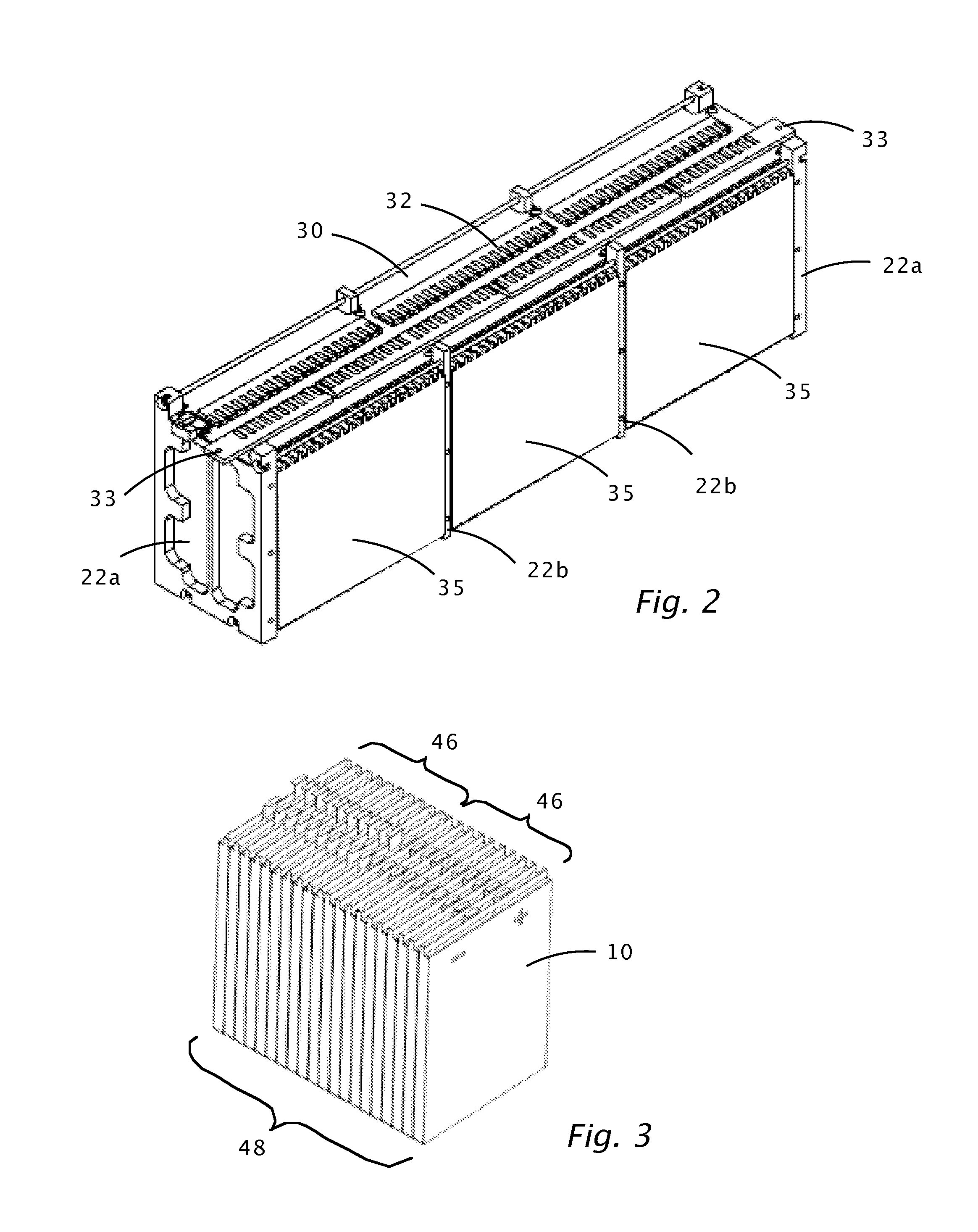
[0056]FIG. 8 shows the slotted bus bars. Bus 32a is a bridge bus which traverses over the polycarbonate lateral plate and connects one double groups of cells 48 to another. Two bridge buses 32a are used in the current embodiment.

[0057]Bus 32b is a normal bus which interconnects the cells wit...


PUM


Abstract

An arrangement of a battery module and a method for making this module are presented. An embodiment is comprised of a plurality of Lithium-ion pouch type unit cells stacked in a linear array. A lightweight frame structure compresses the unit cells and the cells are encapsulated with thermally conductive epoxy. A method of assembly constrains the unit cells during encapsulation such that a thin wall of epoxy is achieved, reducing the thermal resistance of the side walls. A slotted flat panel is placed over the unit cells and the cell tabs protrude through the panel. An arrangement of slotted bus bars reside on the flat panel and the cell tabs are bent at right angles in a manner that allows the tabs to be attached to the bus bars by a soldering or similar means. In an embodiment of the battery module, the flat panel contains battery management circuitry.

Description

CROSS-REFERENCE TO RELATED APPLICATIONS[0001]This patent application claims the benefit of U.S. provisional patent application 61 / 656,326, filed Jun. 6, 2012, which is incorporated by reference along with all other references cited in this application.BACKGROUND OF THE INVENTION[0002]This invention is related to battery modules for electric vehicles. More specifically, the subject of this invention is a battery module containing Lithium-polymer pouch type unit cells and having a thermal management system.[0003]With the trend toward higher pack voltages and the use of Lithium-based batteries, the scope and complexity of fraction battery packs has increased. Depending on the required voltage, a typical battery pack is often comprised of a large number of individual unit cells, these cells being arranged in various series-parallel combinations. It is often desirable to group these cells into modules, which simplifies and standardizes the battery pack assembly process. The modules are t...

Claims


Application Information

Patent Timeline
IPC IPC(8): H01M10/04H01M50/211H01M50/507H01M50/516
CPCH01M10/0468H01M10/0413H01M10/0525Y02E60/10Y02P70/50H01M50/507H01M50/516H01M50/211
Inventor WERRE, JUSTINKLEIN, III, MATTHEW P.ZEVIAR, DANTE
Owner KLEENSPEED TECH
Learn More