Low noise cable providing communication between electronic sensor components and patient monitor

a low-noise, cable technology, applied in the direction of cables, insulated conductors, conductors, etc., can solve the problems of increasing the risk of patient injury, increasing so as to reduce the risk of injury, and avoid injury

Active Publication Date: 2016-01-26
MASIMO CORP
View PDF593 Cites 408 Cited by
  • Summary
  • Abstract
  • Description
  • Claims
  • Application Information

AI Technical Summary

Benefits of technology

[0015]The disclosed opposing rotation of the wires mitigates crosstalk from the opposing rotation. This may be without or in addition to different twist rates or shielding. Opposing rotation in the cable structure may provide a more flexible cable, thereby not hindering sensor placement of the patient.
[0016]In an embodiment, tinsel wires are used to form the cable. Tinsel wires are relatively thin and strong. Using tinsel wires allows the cable to be lighter and more flexible than equivalent all metal wires. While thinner wire is advantageous in some respects, reducing the cable diameter also increases the resistance through the wires. In an embodiment, the tinsel wires may also transmit the high energy drive signals. In such embodiments, the increasing resistance places some limitations on how small the cable diameter can be. The present disclosure accomplishes satisfactory signal transmission while simultaneously reducing the cable diameter.

Problems solved by technology

This is especially problematic because, unlike the known emitter drive signals generated by the monitor, the lower energy detector signal is an unknown signal.
Often, such absorption signals are lower energy signals and thus, often are more easily distorted.
Different twist rates of wire pairs do not fully mitigate crosstalk because at certain points in the cable, the electromagnetic forces of the signals may still interact to cause interference.
While a heavy shield between the wires could potentially reduce the majority of the crosstalk, this makes the cable stiff and thick.
A bulky, cumbersome cable may pull the sensor away from an ideal position on the patient or pull it off altogether, leading to erroneous physiological patient information.
Moreover, heavy shielding is also more susceptible to stress fractures from flexing of the cable, leading to a short lifespan.
Thus, at least because of the foregoing, heavy shielding is at least somewhat of an impractical solution for communicating signals from a sensor to a spectroscopic analysis device.

Method used


Image

  • Low noise cable providing communication between electronic sensor components and patient monitor
  • Low noise cable providing communication between electronic sensor components and patient monitor
  • Low noise cable providing communication between electronic sensor components and patient monitor

Examples


Embodiment Construction

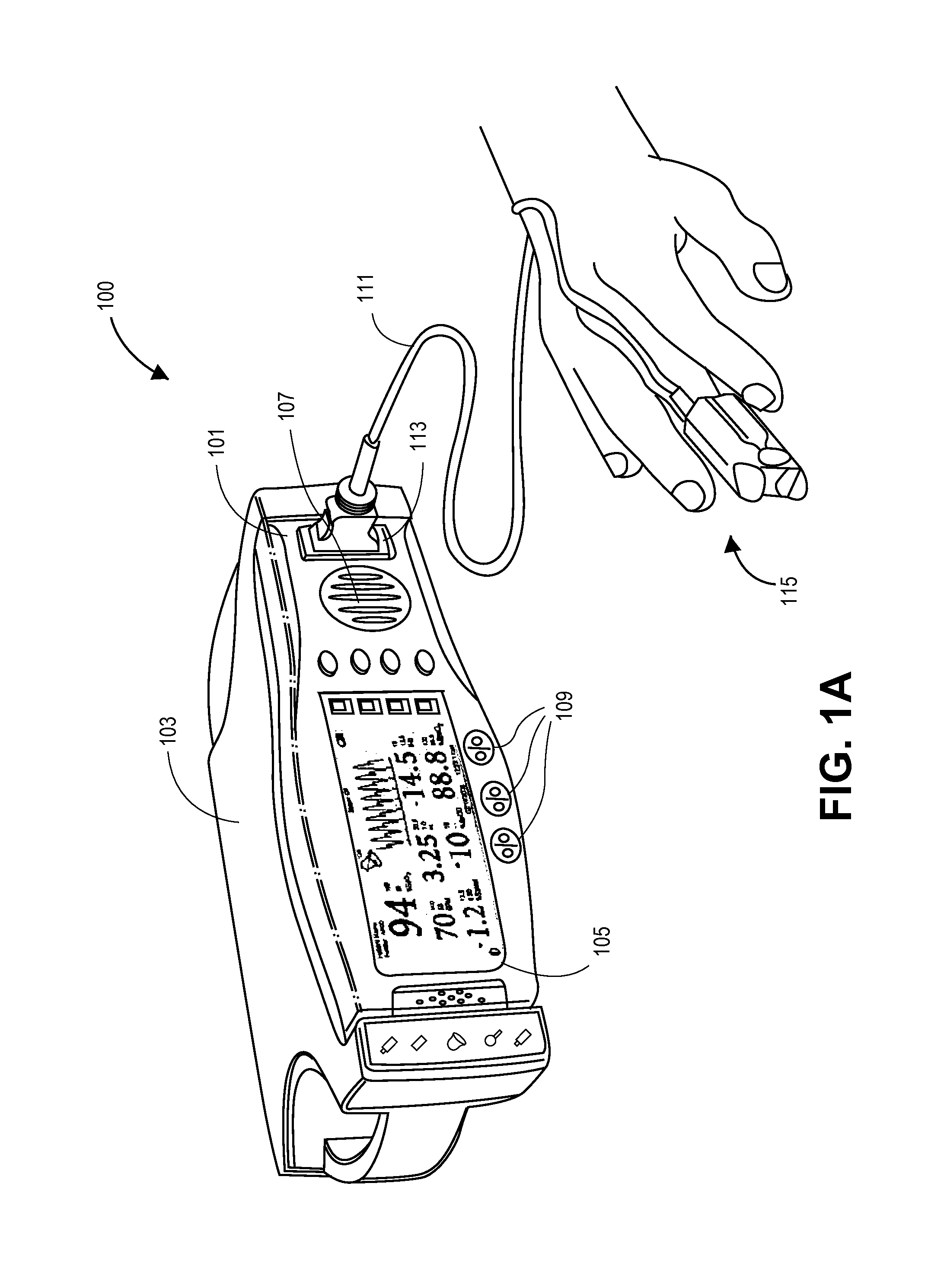
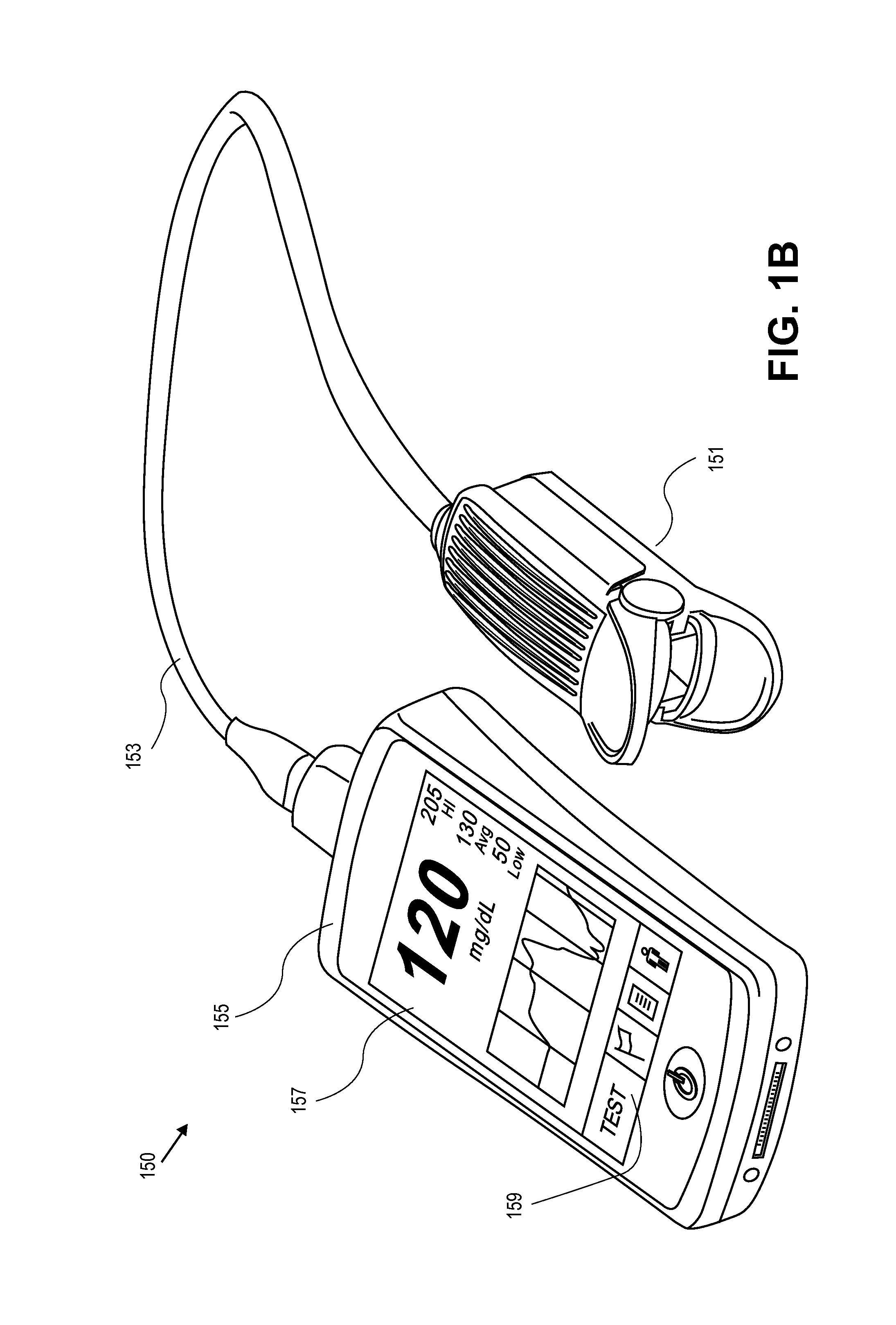
[0026]As shown in FIGS. 1A and 1B (described in more detail below), a physiological measurement systems 100 includes a monitor 101, a cable 111, and a sensor 115. The sensor 115 can be any type of physiological sensor. Illustrated in FIGS. 1A and 1B are embodiments of noninvasive optical sensors. In the case of noninvasive optical sensors, the monitor 101 sends drive signals to one or more emitters in the sensor 115 via the cable 111. The emitters irradiate tissue under observation. One or more detectors in the sensor 115 detect the radiation leaving the tissue and send a signal back to the monitor via the cable responsive to the attenuation. This sequence produces more accurate results when the noninvasive optical sensor 115 remains substantially fixed with respect to the tissue of the patient. In the embodiment where the sensor 115 comprises a reusable sensor, the sensor 115 is often held in place by only the spring action of a clothespin-shaped housing. When a cable is stiff or b...


PUM

PropertyMeasurementUnit
angleaaaaaaaaaa
angleaaaaaaaaaa
angleaaaaaaaaaa

Abstract

A physiological measurement system can include a low noise patient cable that connects a monitor and a noninvasive optical sensor. The cable has a plurality of emitter wires configured to communicate a drive signal between the monitor and at least one emitter. The cable also has a plurality of detector wires configured to communicate a physiological signal between at least one detector responsive to the emitter and the monitor. The emitter and detector wires are orthogonally disposed so that crosstalk between the two functionally different wires is mitigated.

Description

PRIORITY CLAIM[0001]This application claims a priority benefit under 35 U.S.C. §119(e) from U.S. Provisional Patent Application Ser. No. 61 / 502,740, filed on Jun. 29, 2011, titled “Low Noise Patient Cable.” The '740 provisional application is incorporated by reference herein in its entirety.CROSS-REFERENCE TO RELATED APPLICATIONS[0002]The present application is related to U.S. Publication No. 2003 / 0212312, filed on Dec. 19, 2002, entitled “Low Noise Patient Cable,” which is hereby incorporated by reference in its entirety.BACKGROUND OF THE DISCLOSURE[0003]1. Field of the Disclosure[0004]The present disclosure generally relates to patient monitoring devices and more specifically, embodiments of the present disclosure relate to cables connecting a monitor and a sensor of the patient monitoring device.[0005]2. Description of the Related Art[0006]Physiological measurement systems using spectroscopic analysis are a widely accepted noninvasive procedure for measuring patient characteristi...

Claims


Application Information

Patent Timeline
Patent Type & Authority Patents(United States)
IPC IPC(8): H01B7/00H01B11/02H01B11/04
CPCH01B11/00H01B11/02H01B11/04H01B7/00A61B5/1455A61B2562/222A61B2562/227H01B7/1825H01B13/02H01B1/026A61B5/0059A61B5/7203A61B2562/182H01B11/08H01B11/1895H01B13/22
Inventor VO, HUNGDALVI, CRISTIANO
Owner MASIMO CORP
Why Eureka
Try Eureka