Integrated clock gating cell using a low area and a low power latch

a low area and latch technology, applied in the direction of pulse manipulation, logic circuit coupling/interface arrangement, pulse technique, etc., can solve the problem of increasing power consumption

Active Publication Date: 2016-01-26
TEXAS INSTR INC
View PDF4 Cites 10 Cited by
  • Summary
  • Abstract
  • Description
  • Claims
  • Application Information

AI Technical Summary

Benefits of technology

[0005]An embodiment provides a latch. The latch includes a tri-state inverter that receives a latch input and a clock input. An inverting logic gate receives the clock input and an output of the tri-state inverter. The inverting logic gate generates a control signal. The control signal activates the tri-state inverter. A first inverter receives the output of the tri-state inverter and generates a first inverted output. A half tri-state inverter receives the control signal, the clock input and the first inverted output. An output inverter receives the ou...

Problems solved by technology

In advanced digital designs, several clock gating ce...

Method used


Image

  • Integrated clock gating cell using a low area and a low power latch
  • Integrated clock gating cell using a low area and a low power latch
  • Integrated clock gating cell using a low area and a low power latch

Examples


Embodiment Construction

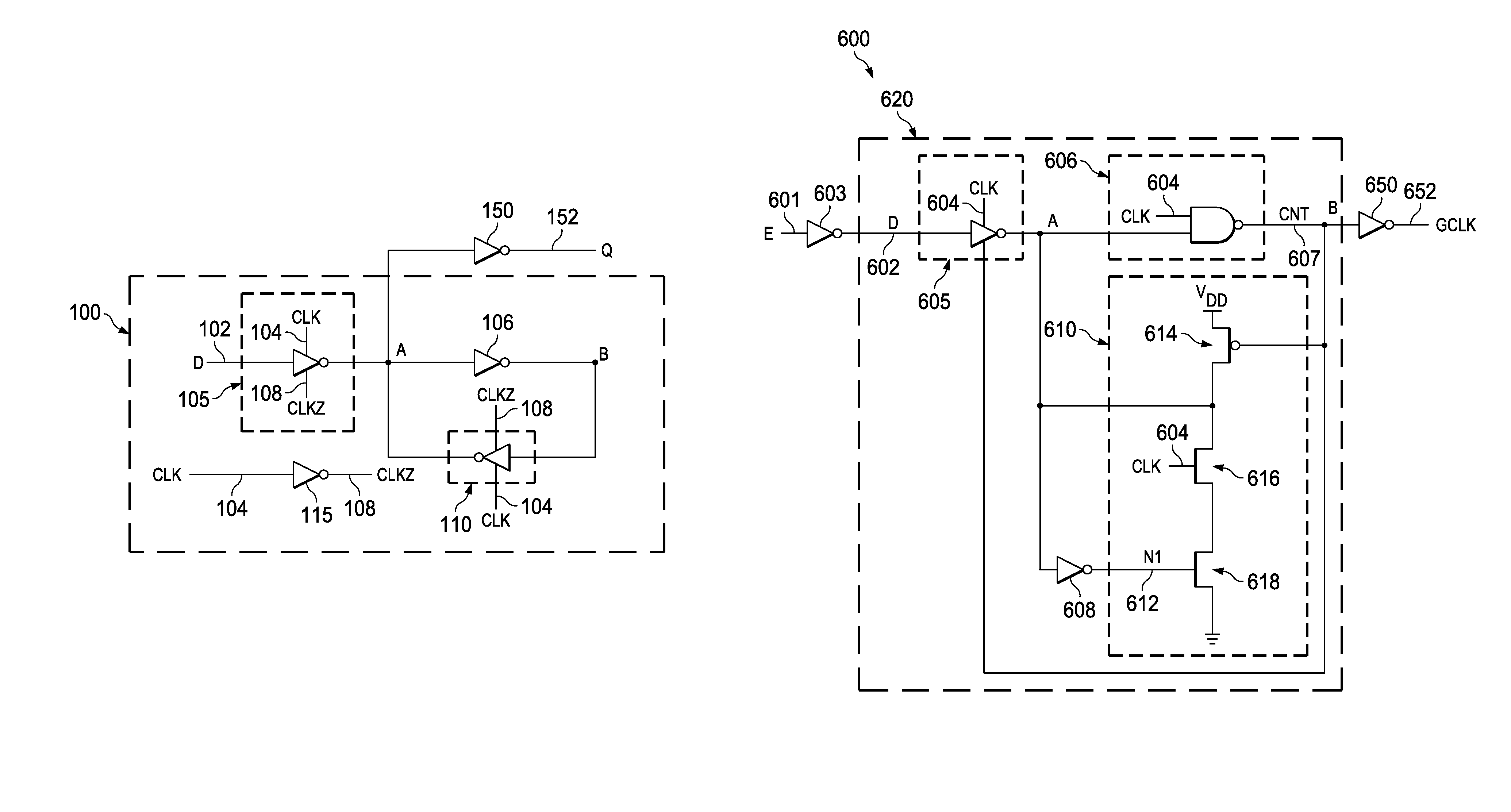
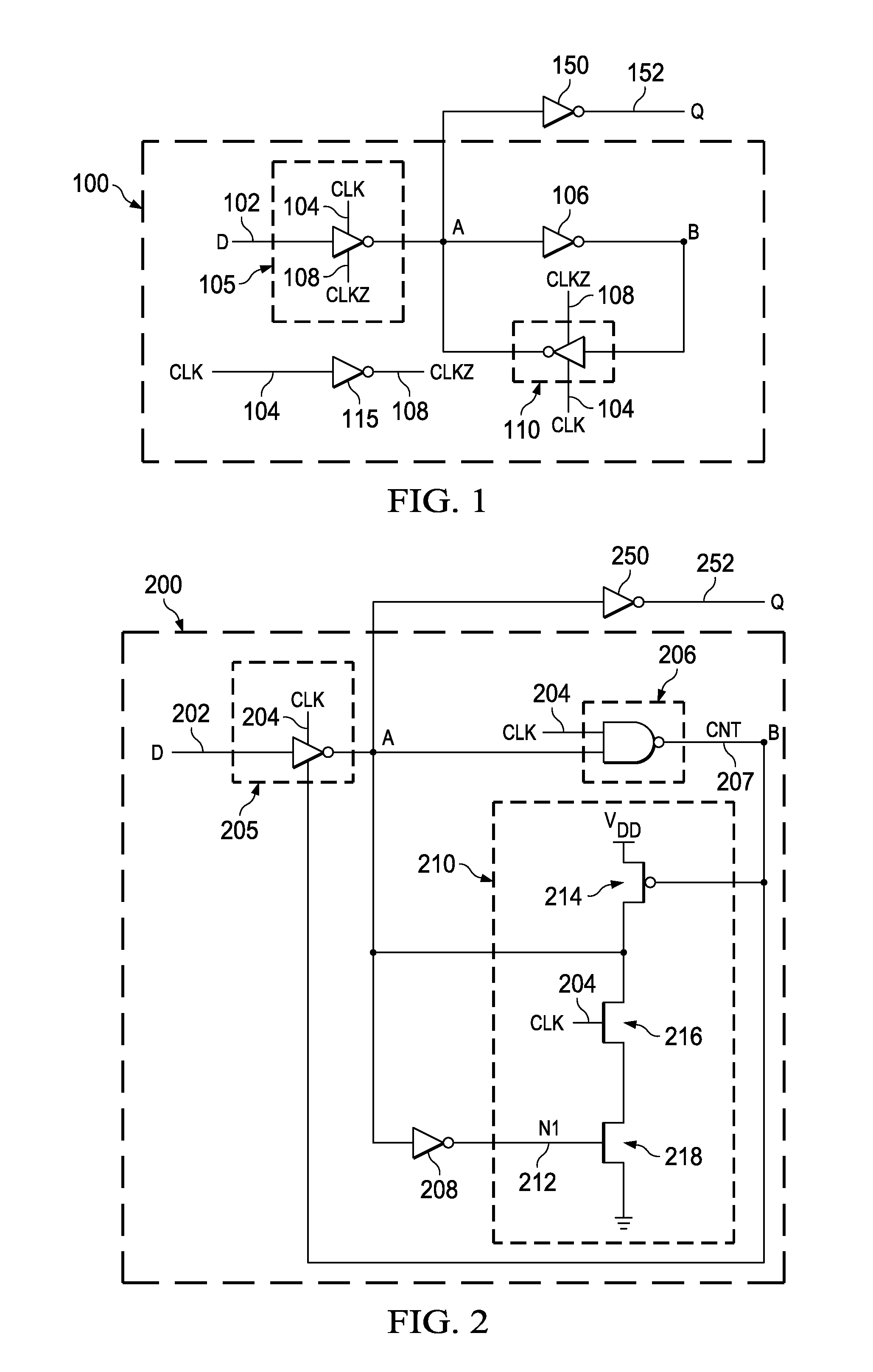
[0015]FIG. 1 illustrates a schematic of a latch 100. The latch 100 includes a first tri-state inverter 105 that receives a latch input D 102, a clock input CLK 104 and an inverted clock input CLKZ 108. A node ‘A’ is coupled to the first tri-state inverter 105. A first inverter 106 is coupled to the node ‘A’. The first inverter 106 receives an output of the first tri-state inverter 105. A node ‘B’ receives an output of the first inverter 106. A second tri-state inverter 110 is coupled to the node ‘B’ and receives the output of the first inverter 106. The second tri-state inverter 110 receives the clock input CLK 104 and the inverted clock input CLKZ 108.

[0016]The node ‘A’ receives an output of the second tri-state inverter 110. An output inverter 150 is coupled to the latch 100. The output inverter 150 is coupled to the node ‘A’ and receives the output of the first tri-state inverter 105. The output inverter 150 generates a latch output Q 152. A second inverter 115 receives the clock...


PUM


Abstract

The disclosure provides an ICG (integrated clock gating) cell that utilizes a low area and a low power latch. The ICG cell includes a first logic gate that receives an enable signal and generates a latch input. A latch is coupled to the first logic gate and receives the latch input and a clock input. The latch includes a tri-state inverter and an inverting logic gate. The tri-state inverter is activated by a control signal generated by the inverting logic gate. A second logic gate receives the control signal and generates a gated clock.

Description

TECHNICAL FIELD[0001]Embodiments of the disclosure relate to a low power latch based integrated clock gating (ICG) cells in an integrated circuit.BACKGROUND[0002]Sequential circuits occupy around 50% of a digital design. Integrated clock gating (ICG) technique is used to reduce power consumption by preventing individual flip flops from switching between logic states when not in use. Thus, the clock power consumption due to clock switching is reduced. In integrated clock gating, the flip flops which are not contributing to the functionality of the circuit are selectively deactivated. The ICG cells are activated or deactivated based on certain conditions. The conditions for disabling the clock cells are a design choice. In advanced digital designs, several clock gating cells are used which results in increased power consumption.[0003]In power critical digital designs, more flip-flops are required to be clock gated which proportionately increases the number of ICG cells in the digital ...

Claims


Application Information

Patent Timeline
IPC IPC(8): H03K19/00H03K19/185H03K5/135H03K3/37H03K3/037H03K19/0185H03K19/096
CPCH03K19/0966H03K5/135H03K19/0013H03K3/0372H03K19/0002H03K19/01855H03K19/0016H03K3/012H03K3/356173
Inventor NANDI, SUVAMSUBBANNAVAR, BADARISH MOHAN
Owner TEXAS INSTR INC
Why Eureka
Try Eureka