
Methods and processes of manufacturing two piece cans

a two-piece, canning technology, applied in the direction of transportation and packaging, rigid containers, other domestic articles, etc., can solve the problems of metal waste, difficult for the canning to be released from the punch, and the self-must be strong enough to withstand

Active Publication Date: 2016-02-09
FARNHAM ENTERPRISES
View PDF15 Cites 13 Cited by
  • Summary
  • Abstract
  • Description
  • Claims
  • Application Information

AI Technical Summary

Benefits of technology

This approach reduces aluminum usage by 1.8 to 2 grams per 12 oz can, decreases environmental impact, and lowers production costs by minimizing chemical usage and die regrinding, while increasing the recyclability and quality of aluminum cans.

Problems solved by technology

However, the can itself has to be strong enough to withstand both internal and external pressures.
But with the punch being new and smooth the coolant and lubricant can't sick to it and a static bond would make it difficult for the can to release from the punch once it is completely drawn out.
Acid etching the entire can causes metal wasting by removing the metal in measureable amounts like tenths of a gram.
Pin holing leaves the can to be recycled and a loss to the total production thus meaning a higher percentage of waste to good cans produced.
The cross hatching can cause the punch to get sludged up with burned coolant waste and lube making it harder for the cans static contact to release.
So the current process has the can industry polluting more water, adding more heavy metals to the our water as well, the cooling process is ineffective and causes the punch to sludge up and not working properly along with causing cross hatching inside of the can which leads to acid etching and material waste.
This gray water has to reclamation process that is very expensive as well as the chemicals they use to clean and etch the can.
This is the process and its many flaws that have been used time and time again.

Method used


Image

  • Methods and processes of manufacturing two piece cans
  • Methods and processes of manufacturing two piece cans
  • Methods and processes of manufacturing two piece cans

Examples


Embodiment Construction

[0019]The following detailed description is of the best currently contemplated modes of carrying out the invention. The description is not to be taken in a limiting sense, but is made merely for the purpose of illustrating the general principles of the invention, since the scope of the invention is best defined by the appended claims.

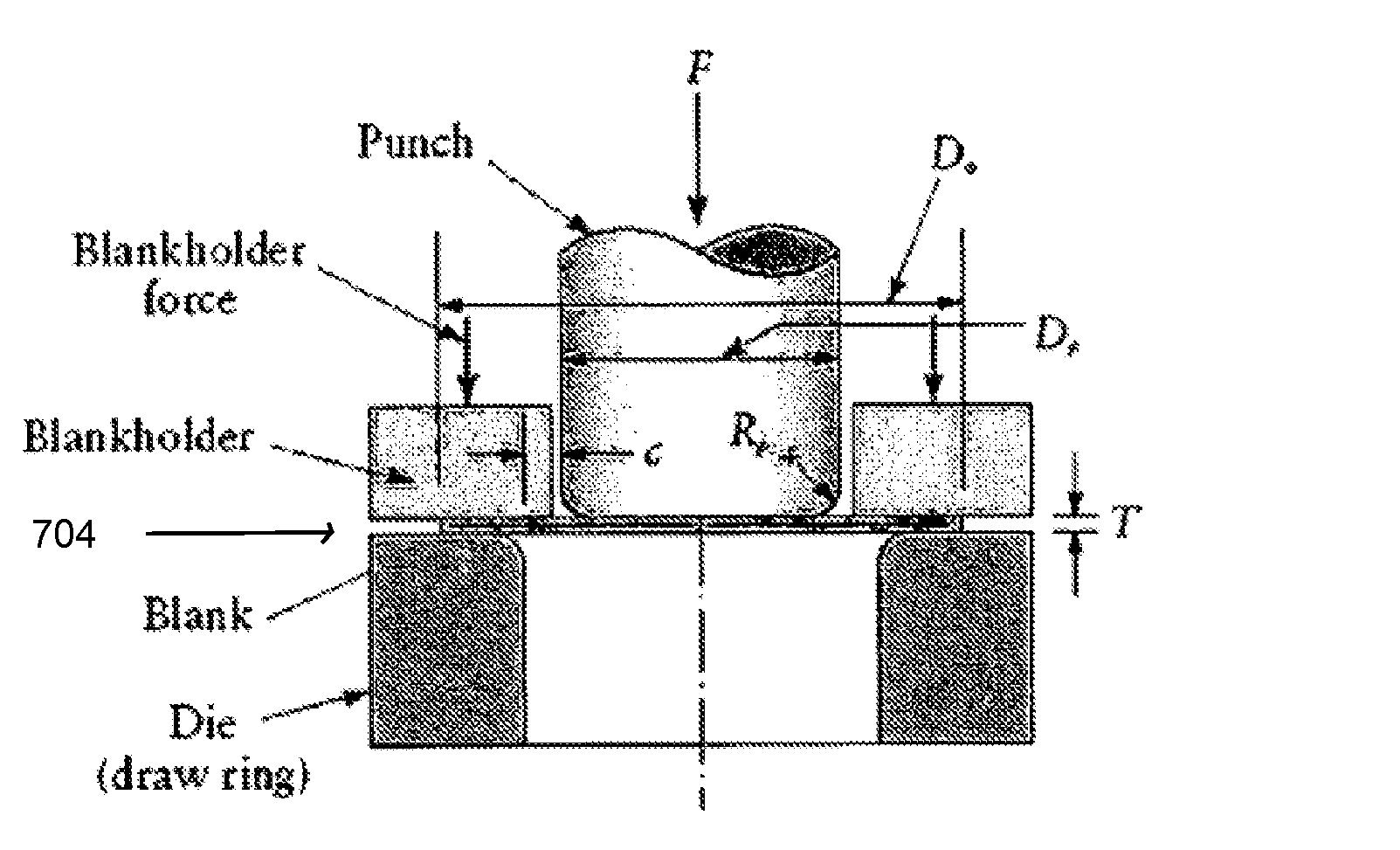
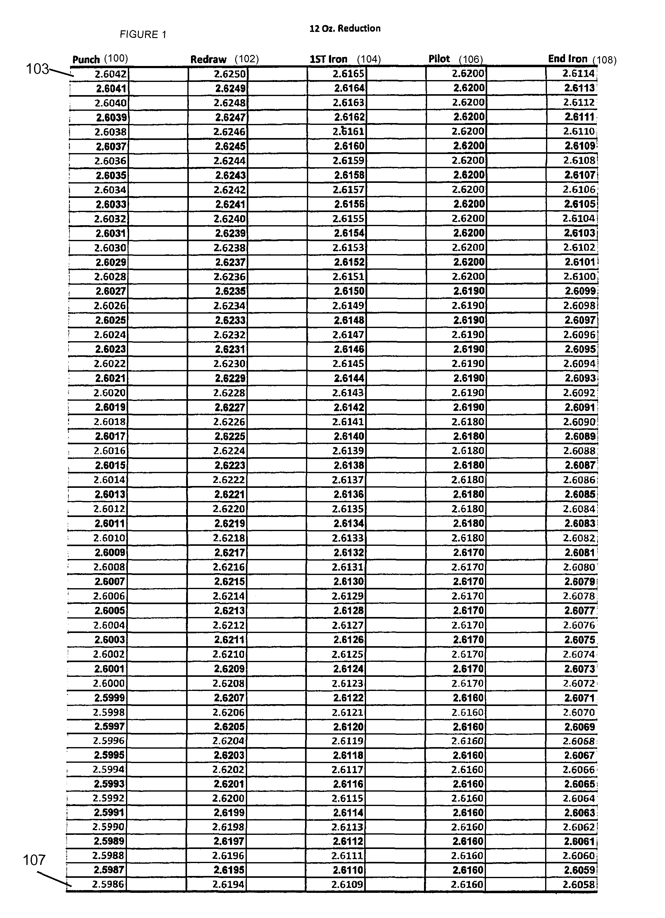
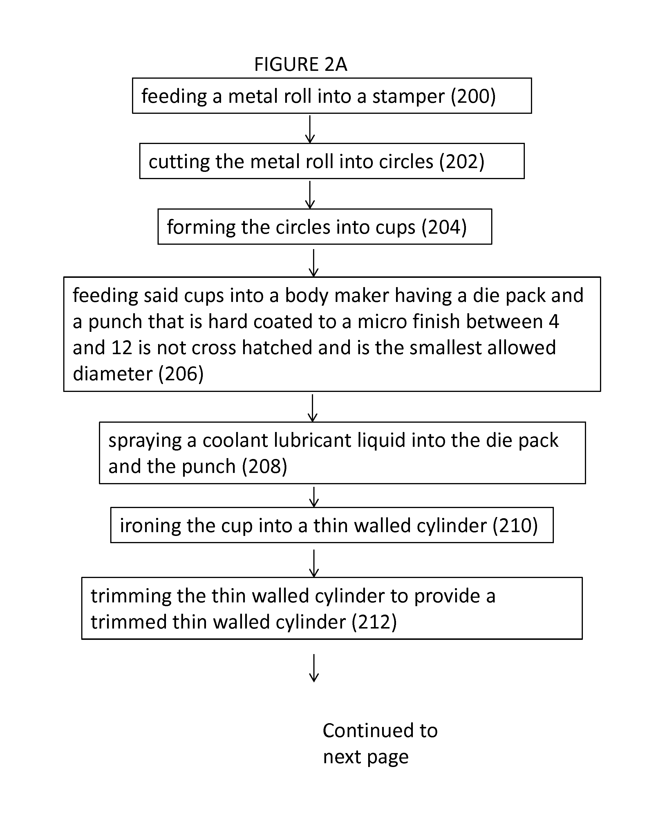
[0020]With reference to FIGS. 2-6, the present invention provides many innovations to reduce the cost of the can, reduce the amount of aluminum in a can, and eliminate hazardous chemicals into our already overburdened ecosystem of our fresh water and reducing the carbon foot print in making the most recycled container (the aluminum can). The present invention solves problems in the body maker through novel ways to help eliminate many undesirable practices and simplify them with a coating on the parts and standardization of the punches and external dies at the minimum size diameter. The following provides a breakdown of the methods and processes accordin...


PUM

PropertyMeasurementUnit
angleaaaaaaaaaa
angleaaaaaaaaaa
angleaaaaaaaaaa

Abstract

A method of drawing and ironing metal into a can comprising the steps of: feeding a metal roll into a stamper; cutting the metal into circles; forming the circles into cups; feeding the cups into a body maker having a die pack with at least three dies and a punch hard coated to a micro finish between 4 and 12, not cross hatched and is the smallest allowed diameter; spraying a coolant lubricant liquid into the die pack and through the punch; ironing the cup into a thin walled cylinder; trimming the thin walled cylinder; washing, rinsing, drying and decorating the trimmed thin walled cylinder; spray coating the inside of the can with a protective coating; necking the trimmed thin walled cylinder; forming a lip on the top of the tapered thin walled cylinder; testing the trimmed thin walled cylinder for defects; and palletizing the thin walled cylinder.

Description

[0001]This application claims priority to provisional patent application No. 61 / 641,808 filed May 2, 2012 and entitled “METHODS AND PROCESSES OF MANUFACTURING TWO PIECE CANS”, the entire contents of which are incorporated herein by reference.[0002]Beverages are commonly served in aluminum and metal cans which are made at the pace of more than one million per day. They are generally formed from two pieces: a top (which generally has a tab for opening the beverage) which is generally affixed to a bottom after it is filled with a liquid substance such as a beer or soda. It is desirable to make the can as thin as possible, to reduce material and shipping costs. However, the can itself has to be strong enough to withstand both internal and external pressures. To do so the cylinder section of the can has many curves in its top and bottom to make the can more rigid and able to withstand the internal and external pressures created by internal gases and external axel loads created by stackin...

Claims


Application Information

Patent Timeline
Patent Type & Authority Patents(United States)
IPC IPC(8): B21D22/28B21D51/26B65D1/16
CPCB21D22/286B21D51/26B65D1/165
Inventor FARNHAM, TIMOTHY, J.
Owner FARNHAM ENTERPRISES
Learn More