Aircraft energy management system including engine fan discharge air boosted environmental control system

a technology of environmental control system and engine, which is applied in the direction of energy-efficient board measures, machines/engines, and efficient propulsion technologies, can solve the problems of significant increase in size, limited temperature capability of structures compared to metal alloys, and inability to meet the requirements of engine bleed air, so as to reduce ram air drag losses and minimize overall aircraft weight

Active Publication Date: 2016-02-09
EMBRAER SA
View PDF13 Cites 20 Cited by
  • Summary
  • Abstract
  • Description
  • Claims
  • Application Information

AI Technical Summary

Benefits of technology

[0006]These and other shortcomings of the prior art are addressed by the present disclosure, which provides an aircraft energy management system that provides an engine fan discharge air boosted aircraft environmental control system which is effective to extract fan discharge air from a turbine engine and provide airflow to an aircraft environmental control system. The aircraft energy management system is configured to benefit from the fan pressure ratio and reduced ram air drag losses, while minimizing overall aircraft weight.

Problems solved by technology

These structures have limited temperature capability compared to metal alloys.
Conventional ECS interfaces, utilizing engine bleed air cannot meet this requirement without significantly increasing the size of an included precooler.
The electrical power requirements can require an undesirable increase in the size of the engine mounted generators.
In addition, the air intakes will produce drag on the aircraft, translating to an increase in fuel burn and therefore cost of operation.
These weight and drag penalties of electrically driven ECS are also of concern in smaller aircraft.

Method used


Image

  • Aircraft energy management system including engine fan discharge air boosted environmental control system
  • Aircraft energy management system including engine fan discharge air boosted environmental control system
  • Aircraft energy management system including engine fan discharge air boosted environmental control system

Examples


Embodiment Construction

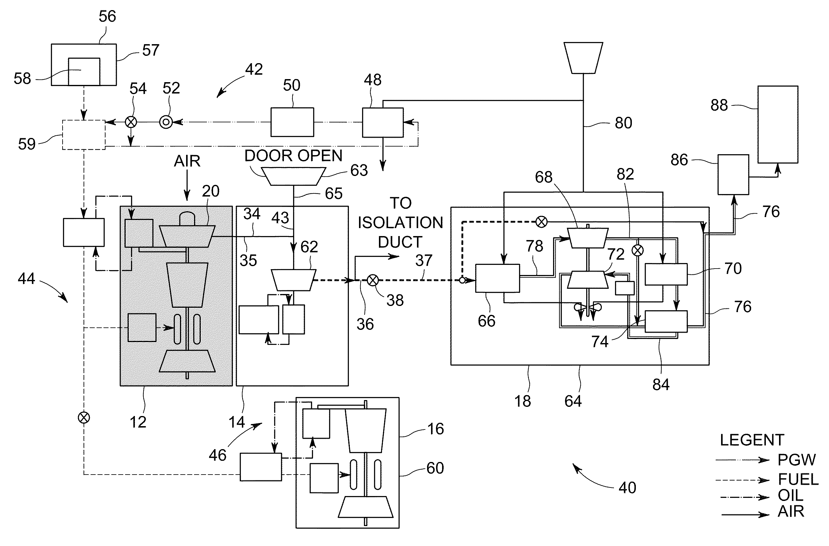
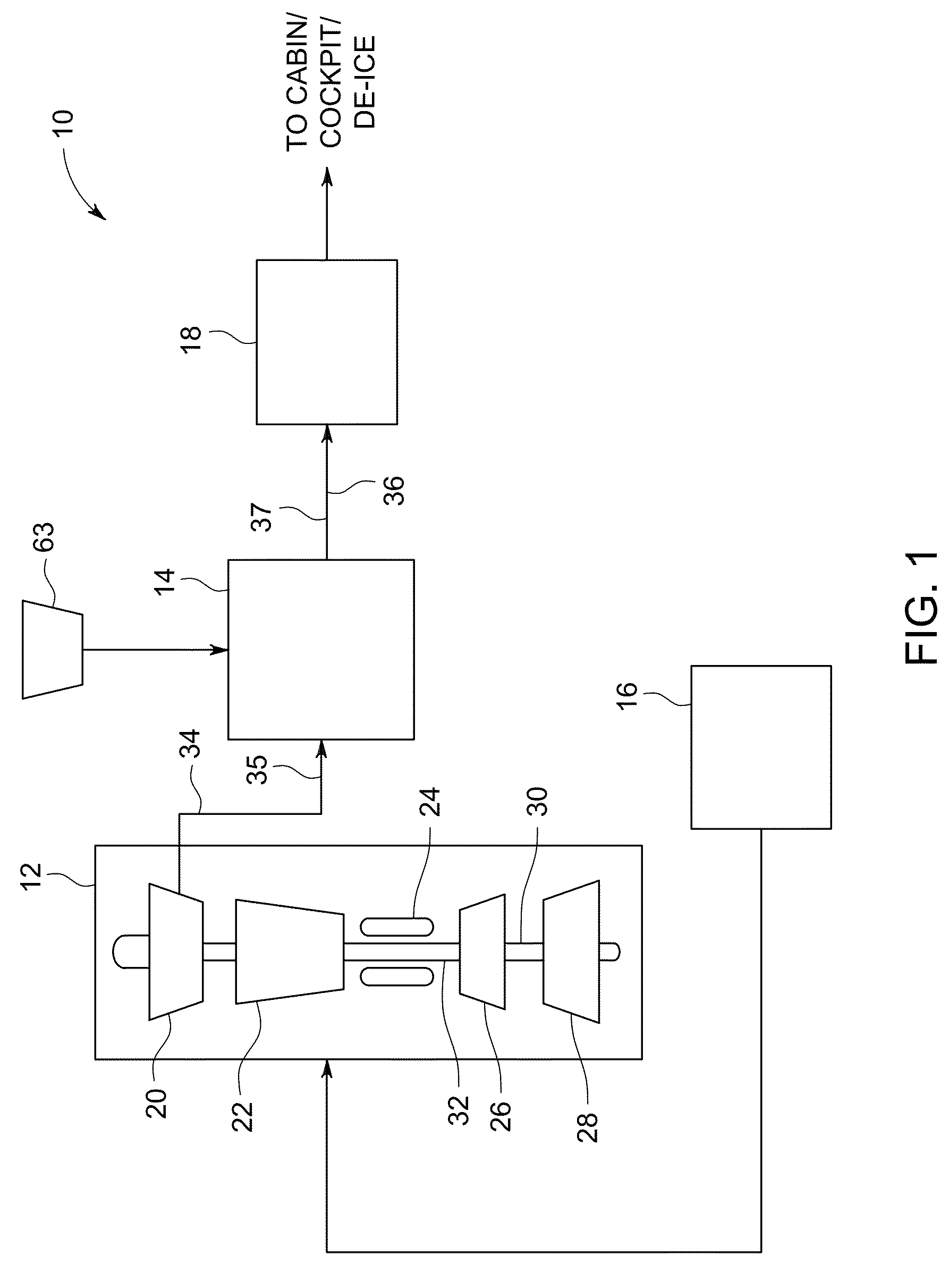
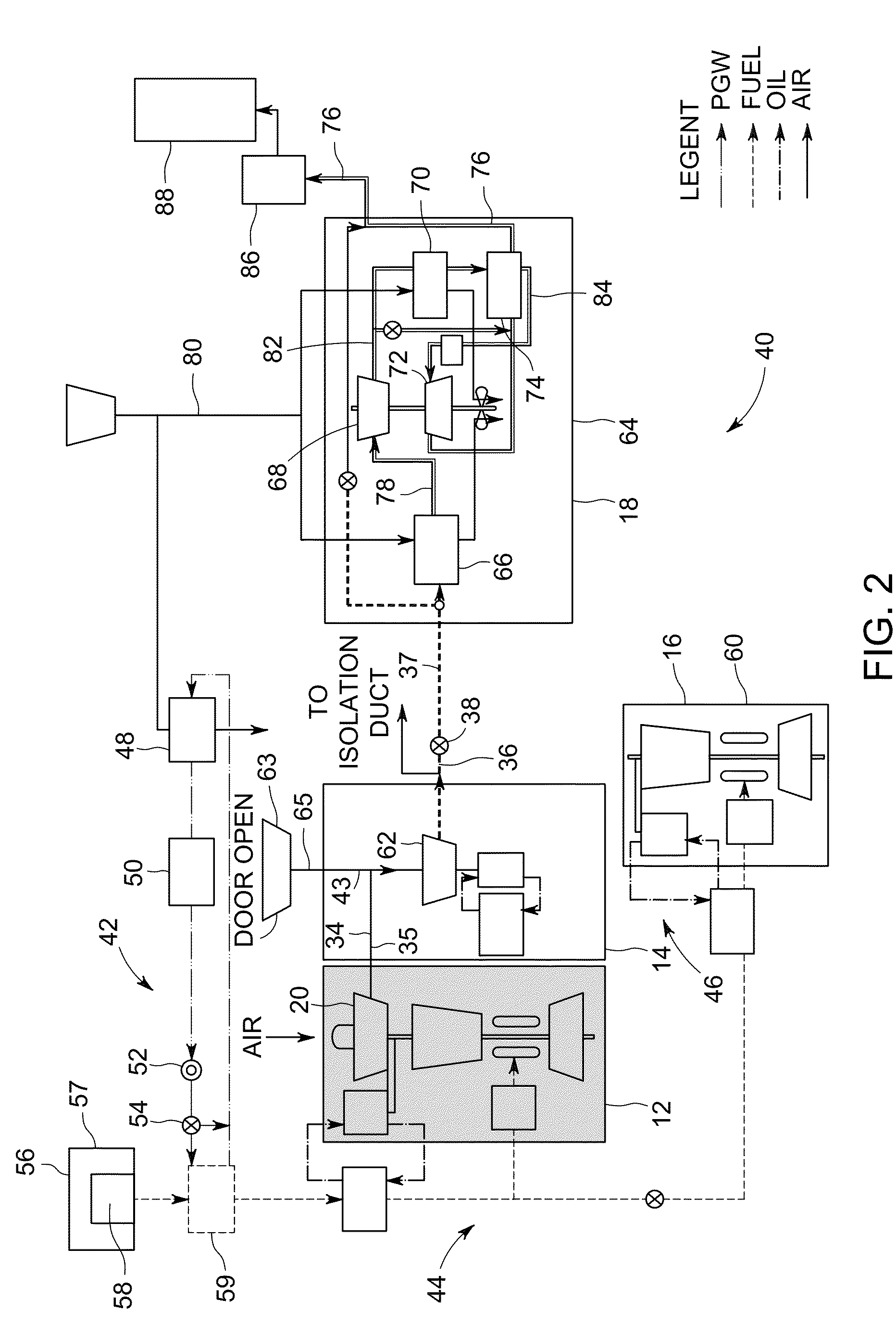
[0020]Referring to the drawings wherein identical reference numerals denote the same elements throughout the various views, FIG. 1 depicts in a simplified block diagram, elements of an exemplary aircraft energy management system 10 including a gas turbine engine 12 in fluidic communication with an electrically driven cabin air compressor (CAC) 14, a means for providing ground power 16 and an environmental control system (ECS) 18. The engine 12 having an engine fan 20, a high pressure compressor 22, a combustor 24, a high pressure turbine 26, and a low pressure turbine 28, all arranged in a serial, axial flow relationship. Collectively the high pressure compressor 22, the combustor 24, and the high pressure turbine 26 are referred to as a “core”25. The fan 20 providing intake air to the high pressure compressor 22. The high pressure compressor 22 provides compressed air that passes into the combustor 24 where fuel is introduced and burned, generating hot combustion gases. The hot com...


PUM


Abstract

An aircraft energy management system including a cabin air compressor adapted to be coupled to a source of fan discharge air at a first pressure during an inflight operating mode and adapted to be coupled to a ram intake air during a ground operating mode. The system further including an environmental control system mechanically coupled to a compressor exit of the cabin air compressor. The aircraft energy management system configured to provide a conditioned fluid flow to an aircraft cabin, cockpit or de-icing system.

Description

BACKGROUND[0001]Embodiments disclosed herein relate generally to aircraft energy management systems including environmental control systems and more particularly to methods and apparatus for extracting fan discharge air to boost an aircraft environmental control system.[0002]Turbine-powered aircraft conventionally incorporate environmental control systems (ECS) which control aircraft cabin temperature by the amount and temperature of a bleed air extracted from an engine. Historically, ECS have used engine bleed air that is extracted from a high pressure compressor (HPC) or is generated by means of a compressor that is driven by an auxiliary gas turbine (“APU”), throttled (pressure reduced), and cooled by a heat exchanger (“precooler”) using fan bleed air. Bleed air is also used to provide anti-icing to the aircraft, and must be at high temperature for this purpose—typically about 204° C. (400° F.).[0003]Aircraft weight is a current concern in the current industry, with a decrease in...

Claims


Application Information

Patent Timeline
Patent Type & Authority Patents(United States)
IPC IPC(8): B64D13/06F02C6/08F02K3/06B64D15/04
CPCB64D13/06F02C6/08F02K3/06B64D15/04B64D2013/0607B64D2013/0618Y02T50/44Y02T50/56Y02T50/672Y02T50/40Y02T50/50Y02T50/60
Inventor ZHOU, RUIWINTER, STEPHEN FRANCISKYRIAZOPOULOS, ATHANASIOSMULLER, JONES RICARDOPARILLA, JAVIER ARMANDO
Owner EMBRAER SA
Why Eureka
Try Eureka