Drive arrangement

a technology of driving arrangement and drive shaft, which is applied in the direction of mechanical equipment, transportation and packaging, and transportation of goods, can solve the problems of difficult accommodation in the motor vehicle, and achieve the effects of favorable transmission efficiency, high drive torque of the electric machine, and high transmission ratio

Active Publication Date: 2016-02-09
AUDI AG
View PDF21 Cites 16 Cited by
  • Summary
  • Abstract
  • Description
  • Claims
  • Application Information

AI Technical Summary

Benefits of technology

[0006]According to one aspect of the present invention, a drive arrangement includes a differential having an input element and output elements, wherein the output elements are operably connected to the wheels of the motor vehicle via output shafts; a gear mechanism, and an electric machine having a ring shaped rotor, wherein the ring shaped rotor defines a rotation axis of the electric machine and is connected in driving relationship with the input element of the differential via the gear mechanism, and wherein the ring shaped rotor and the gear mechanism are integrated in the rotor. This results in a particularly compact and with regard to manufacturing favorable construction of the drive arrangement, which in addition is also well adjustable to narrow mounting spaces. The gear mechanism which is interposed there between allows sufficiently high drive torques of the electric machine at moderate constructional efforts.
[0007]According to another advantageous feature of the invention, the gear mechanism can be constructed as a planet gear train having a housing-fixed reaction element and another input element in driving relationship with the rotor, wherein the rotor can have an output element drivingly connected to the input element of the differential. Such a planet gear train allows realizing high transmission ratios at a favorable transmission efficiency and at a relatively small installation space. In an advantageous layout of the planet gear train, the other input element of the gear mechanism can be an internal gear which is arranged in a hollow shaft of the rotor, the output element can be a planet gear carrier with planet gears and the reaction element can be a housing-fixed sun gear.
[0008]In a particularly advantageous refinement of the invention, the differential and the gear mechanism can be supported coaxial to the rotor of the electric machine via intermediate shafts which are connected to the output elements of the differential and, via two further gear mechanisms, output to output shafts which are supported offset to the rotation axis of the electric machine. The further gear mechanisms enable a still greater layout of the overall transmission ratio of the drive arrangement and in particular have the advantage that the electric machine with integrated differential is offset in particular upwards relative to the rotation axes of the output shafts and thus ensures sufficient ground clearance of the drive arrangement in the motor vehicle.
[0009]For easy manufacturing, the two further gear mechanisms can be positioned outside and on both sides of the electric machine and can in particular be formed by pinions on the intermediate shafts and by internally toothed internal gears on the output shafts. Thereby, the gear mechanisms can be produced as pre-assembly units and mounted to the electric machine and the differential via plug-in connections. Instead of the internal gears which mesh with the pinions pure spur gear systems can also be used as gear mechanisms.
[0010]According to another advantageous feature of the invention, the gear mechanism which is integrated in the electric machine and acts on the differential can be shiftable into a driveless neutral position or into at least one transmission stage via a shifting device. This allows further degrees of freedom in the transmission layout of the drive arrangement at a structurally and constructively little additional effort, and in addition enables a disengagement of the electric machine in the neutral position of the shifting device, which can be particularly advantageous in a hybrid drive of the motor vehicle for example during operation of the internal combustion engine.
[0011]According to another advantageous feature of the invention, the reaction element of the gear mechanism or respectively the planet gear train can be shiftable by the shifting device between three positions, a first position in which the reaction element is housing-fixed, a second position in which the reaction element is freely rotatable, and a third position in which the reaction element is coupled to the input element. Beside the disengagement function, this results in two transmission stages, namely a transmission ratio which increases the torque, and a 1:1 transmission ratio which is advantageous for the higher speed range of the motor vehicle.

Problems solved by technology

If the electric machine is to have a high torque or respectively a high driving power the accommodation in the motor vehicle can be problematic.

Method used


Image

  • Drive arrangement
  • Drive arrangement
  • Drive arrangement

Examples


Embodiment Construction

[0019]Throughout all the Figures, same or corresponding elements are generally indicated by same reference numerals. These depicted embodiments are to be understood as illustrative of the invention and not as limiting in any way. It should also be understood that the drawings are not necessarily to scale and that the embodiments are sometimes illustrated by graphic symbols, phantom lines, diagrammatic representations and fragmentary views. In certain instances, details which are not necessary for an understanding of the present invention or which render other details difficult to perceive may have been omitted.

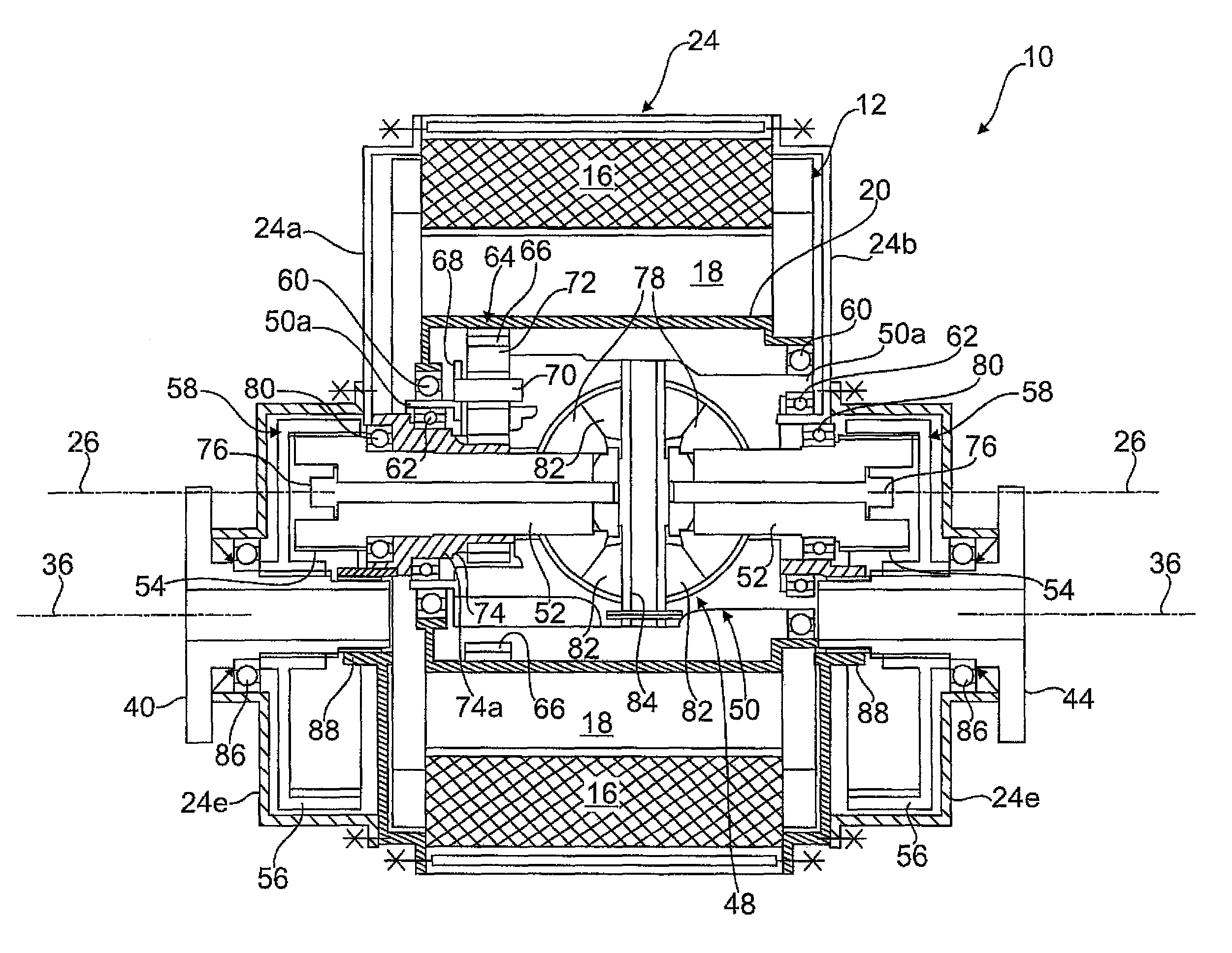
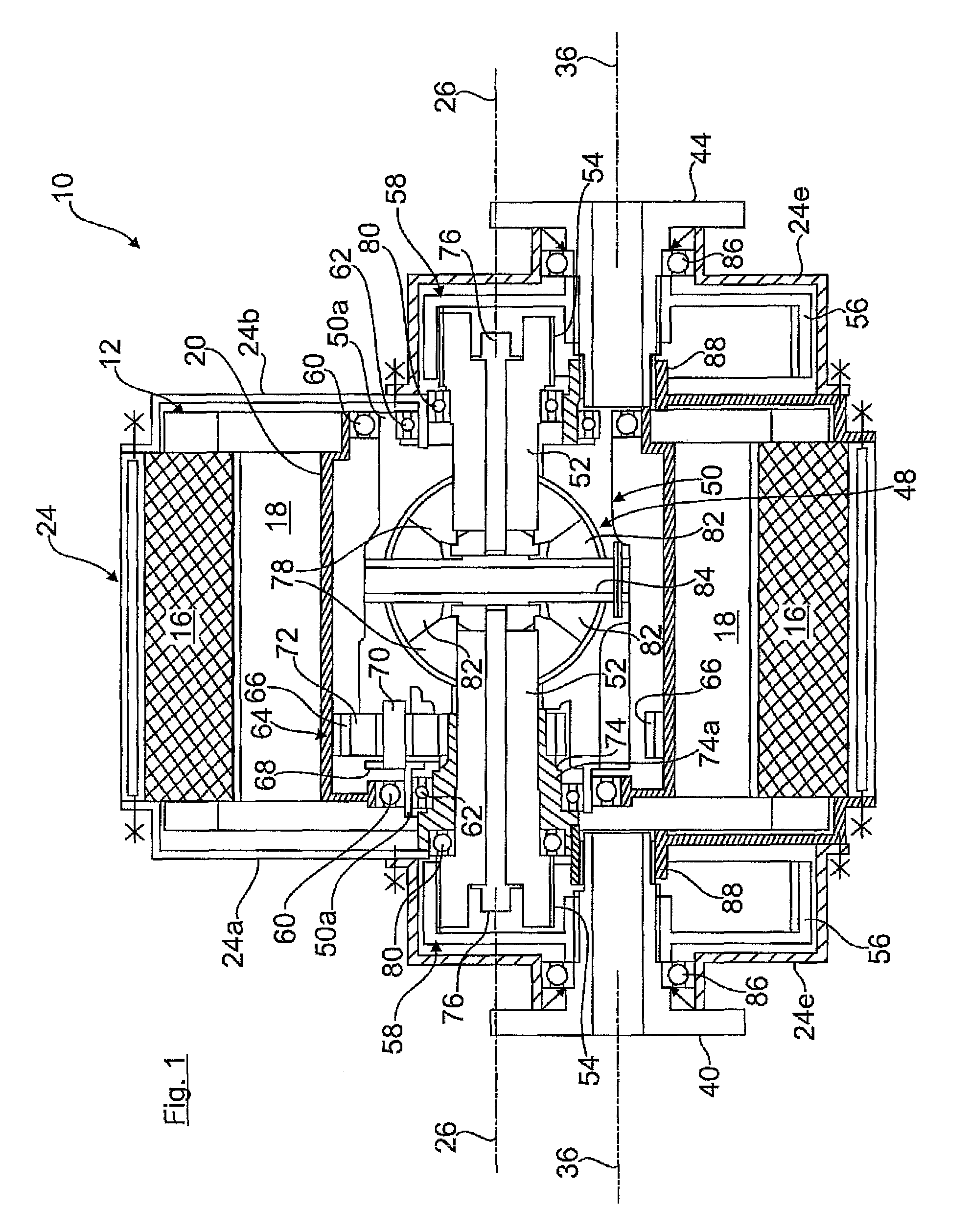
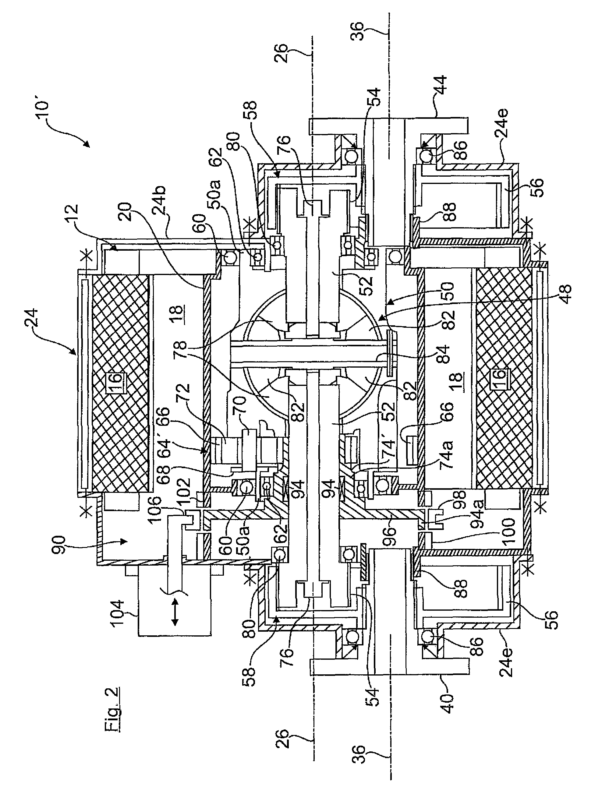
[0020]Turning now to the drawing, and in particular to FIG. 1, there is shown a drive arrangement for an electrically driven axle (for example a front axle or a rear axle) of a motor vehicle which is designated 10, and which is formed inter alia by an electric machine 12, a planet gear train 64 as integrated gear mechanism and a bevel gear differential 48 which is also integra...


PUM


Abstract

In a drive arrangement for wheels of a motor vehicle which are driven by an electric machine via a differential, an electric machine which has a ring shaped rotor drives a drive element of the differential, whose output shafts output to the wheels of the motor vehicle. The ring shaped rotor of the electric machine outputs to the input element of the differential via a gear mechanism and the differential is integrated in the rotor thereby allowing for a structurally compact construction and enabling favorable transmission ratios.

Description

CROSS-REFERENCES TO RELATED APPLICATIONS[0001]This application claims the priority of German Patent Application, Serial No. 10 2011 100 816.4, filed May 6, 2011, pursuant to 35 U.S.C. 119(a)-(d), the disclosure of which is incorporated herein by reference.BACKGROUND OF THE INVENTION[0002]The present invention relates to a drive arrangement for wheels of a motor vehicle which are driven by means of an electric machine via a differential.[0003]The following discussion of related art is provided to assist the reader in understanding the advantages of the invention, and is not to be construed as an admission that this related art is prior art to this invention.[0004]In electrically driven motor vehicles or hybrid drives it is know to drive an axle of the motor vehicle by means of an electromotor or an electric machine (which is also operable as a generator during braking) via a customary differential. If the electric machine is to have a high torque or respectively a high driving power ...

Claims


Application Information

Patent Timeline
Patent Type & Authority Patents(United States)
IPC IPC(8): B60K17/16F16H48/06B60K7/00
CPCF16H48/06B60K7/0007B60K17/165
Inventor MARKL, JOHANN
Owner AUDI AG
Why Eureka
Try Eureka