Regenerative braking system for a hybrid electric vehicle and a corresponding method

a hybrid electric vehicle and regenerative braking technology, applied in the direction of braking systems, braking components, transportation and packaging, etc., can solve the problems of limiting or decreasing the regenerative braking torque, difficult to achieve the braking force, and driver's unsatisfactory sense of security with respect to the functional and capacity of the braking system, so as to achieve a cost-effective and reliable regenerative braking system

Active Publication Date: 2016-02-23
VOLVO CAR CORP
View PDF16 Cites 10 Cited by
  • Summary
  • Abstract
  • Description
  • Claims
  • Application Information

AI Technical Summary

Benefits of technology

[0005]The object of the present invention is to provide an inventive regenerative braking system for a hybrid electric vehicle where the previously mentioned problems are at least partly avoided. This object is achieved by a system for controlling regenerative braking of a hybrid electric vehicle. The system comprises a braking system having a brake pedal suitable for being operated by a driver, a hydraulically actuated friction brake at at least one front wheel, an anti-lock braking system hydraulically connected to said hydraulically actuated friction brake, and an electrically actuated friction brake at at least one rear wheel. The system further comprises an electric machine connected to said at least one rear wheel and capable of performing regenerative braking of said at least one rear wheel, and an electronic control unit that controls the stability of said hybrid electric vehicle, wherein said electronic control unit is configured to provide increased braking torque of said front hydraulically actuated friction brake by means of said anti-lock braking system for compensating a decreased or limited rear wheel braking torque initiated by said electronic control unit.
[0008]Consequently, if an elevated risk of vehicle instability is determined, the electronic control unit may decide to limit or decrease the regenerative braking torque, such that the driver may experience a loss of braking force without having released the brake pedal, or at least a loss of braking force that is unproportional to the brake pedal motion. The change in vehicle brake torque might thus be independent from a corresponding change in brake pedal motion. The loss of vehicle braking torque results in driver discomfort and insecureness as to the reliability and proper function of the vehicle brake system. The invention solves this problem by providing a regenerative braking system that is configured to automatically compensate a decreased or limited rear wheel braking torque that is initiated by said electronic control unit for stability reasons. The automatic compensation involves providing increased braking torque of said front hydraulically actuated friction brake for compensating a decreased or limited rear wheel braking torque. The increased level of front wheel hydraulic braking torque preferably completely corresponds to the decreased or limited level of rear wheel regenerative braking torque. The increased level of front wheel hydraulic braking torque is provided by means of the standard vehicle anti-lock braking system because then no additional electro-hydraulic equipment is necessary, resulting in a more economical solution.
[0012]In one of the advantageous aspect of the invention said at least one rear wheel is free from hydraulically actuated friction brakes. This enables a more economical product solution where an expensive and service demanding rear wheel hydraulic braking system can be completely avoided. This solution also enables providing the brake system with an advantageous initial brake pedal motion gap, as described in more detail below.
[0013]Said at least one front wheel is mechanically disconnected from the electrical machine, such that the electrical machine only can provide regenerative braking torque by means of the at least one rear wheel. By avoiding any rotational couplings between the front wheels and the electrical machine, further cost savings are provided. This also enables a more functionality oriented localisation of the electrical machine and electrical storage unit, such as a battery, close to the rear wheels, for the purpose of further reducing manufacturing costs and weight of the vehicle.
[0014]According to an advantageous aspect of the invention the brake pedal is provided with an initial brake pedal motion gap, in which the motion of the brake pedal is independent from the motion of at least one piston of a master brake cylinder of the hydraulic braking system, such that no vehicle braking torque is applied by the hydraulically actuated friction brake of said at least one front wheel upon actuation of the brake pedal within said initial brake pedal motion gap. This arrangement solves the combined hydraulic and regenerative braking in an efficient and cost effective manner. During the initial brake pedal motion from a rest position, the brake pedal is within said initial brake pedal motion gap. Within this gap, motion of the brake pedal does not result in any front wheel hydraulic brake torque. Instead, the brake pedal depression level is sensed by means of a sensor, such as an angle sensor. Sensor data about brake pedal depression is transmitted to an electronic control unit that subsequently controls the electrical machine and rear electrical to provide a brake torque substantially corresponding to desired brake torque from the vehicle driver. Vehicle driver desired brake torque within the initial brake pedal motion gap may be determined using a predetermined brake torque function that uses brake pedal depression level as input.
[0020]By means of providing an almost standard hydraulic brake system to the front wheels, no additional expensive and complex electro-mechanical brake torque distribution devices are necessary to provide an efficient combined hydraulic and regenerative braking system. Merely an initial brake pedal motion gap with belonging sensor is required to achieve an fully operational regenerative braking system. Hence, a cost-effective and reliable regenerative braking system is provided.

Problems solved by technology

However, such desired braking force is difficult to achieve by means of combined hydraulic and regenerative braking systems, such that the driver may feel unsecure with respect to the functional and capacity of the braking system.
Consequently, if an elevated risk of vehicle instability is determined, the electronic control unit may decide to limit or decrease the regenerative braking torque, such that the driver may experience a loss of braking force without having released the brake pedal, or at least a loss of braking force that is unproportional to the brake pedal motion.
The loss of vehicle braking torque results in driver discomfort and insecureness as to the reliability and proper function of the vehicle brake system.
Over-braked rear wheels result when too high brake torque is applied to rear brakes compared with applied front brake torque.

Method used


Image

  • Regenerative braking system for a hybrid electric vehicle and a corresponding method
  • Regenerative braking system for a hybrid electric vehicle and a corresponding method
  • Regenerative braking system for a hybrid electric vehicle and a corresponding method

Examples


Embodiment Construction

[0028]Various aspects of the invention will hereinafter be described in conjunction with the appended drawings provided to illustrate and not to limit the invention, wherein like designations denote like elements, and variations of the aspects are not restricted to the specific shown aspect, but are applicable on other variations of the invention.

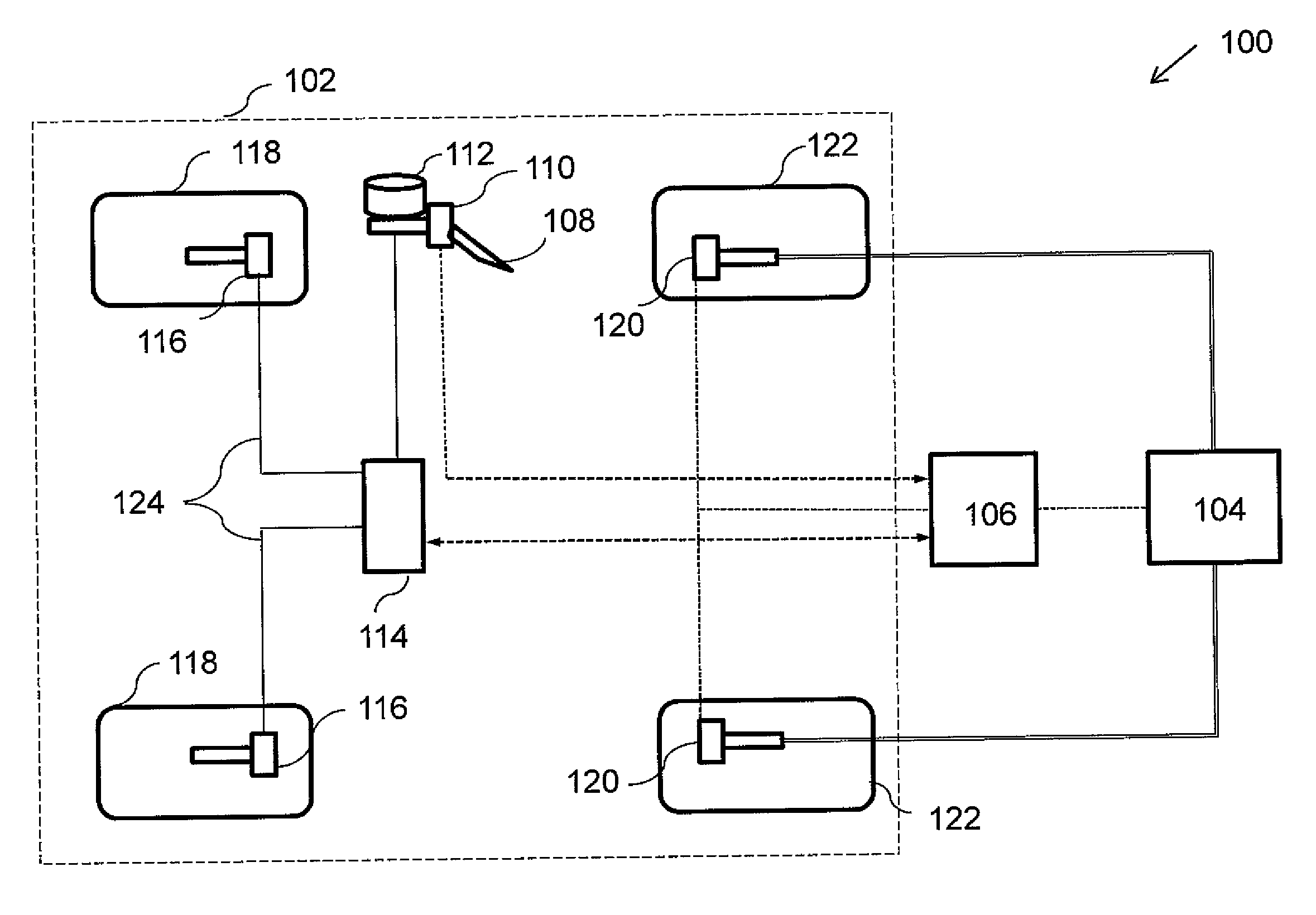
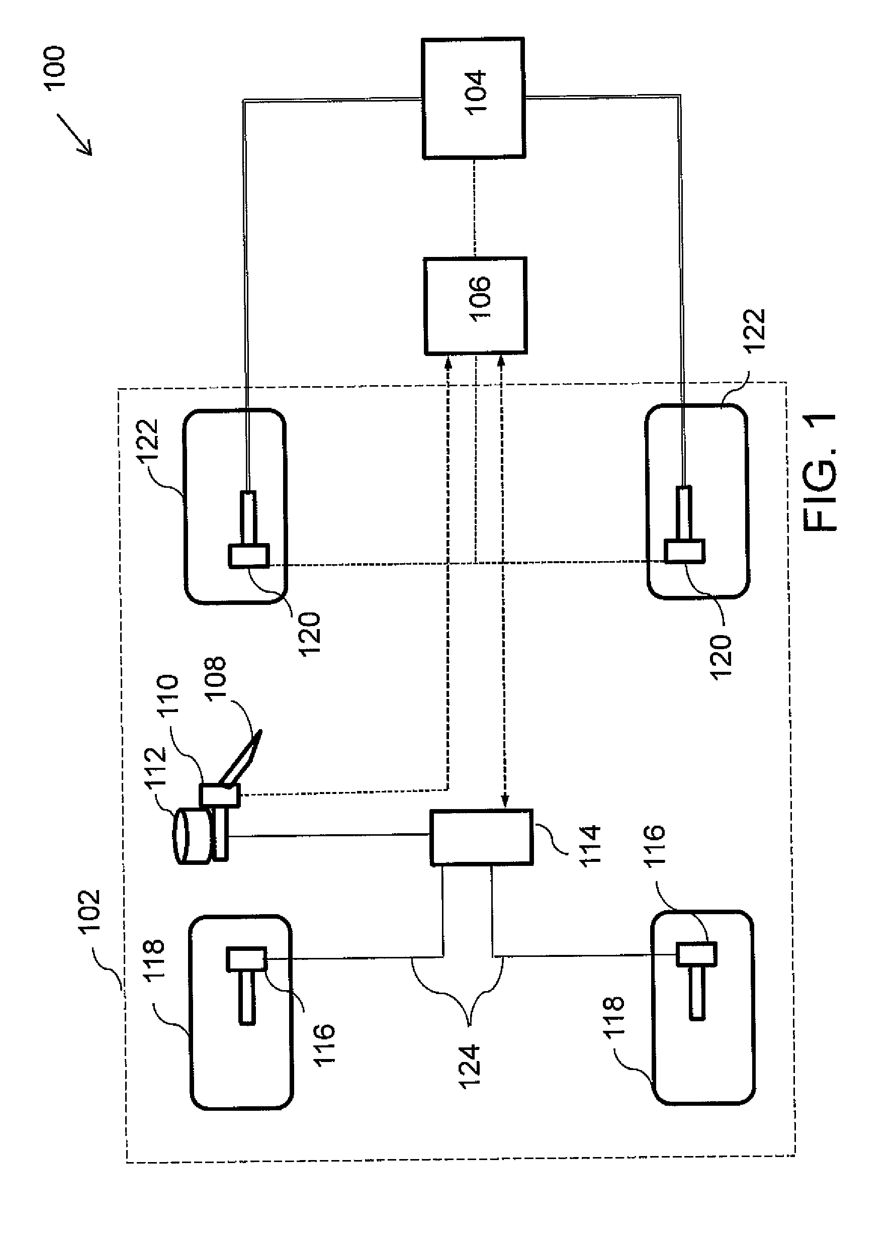
[0029]FIG. 1 illustrates a schematic diagram of a regenerative braking system 100 for a hybrid electric vehicle according to the present invention. The regenerative braking system 100 as shown in FIG. 1 comprises a braking system 102, an electric machine 104 and an electronic control unit (ECU) 106.

[0030]The braking system 102 comprises a brake pedal 108, a hydraulic master cylinder assembly 110, a reservoir for hydraulic fluid 112, an anti-lock braking system 114, hydraulically actuated friction brakes 116 at front wheels 118 of the vehicle and electrically actuated friction brakes 120 at rear wheels 122 of the vehicle, which typically is ...


PUM


Abstract

A method and system for controlling regenerative braking of a hybrid electric vehicle. The regenerative braking system includes a driver-operable brake pedal, a hydraulically actuated friction brake for at least one front wheel, an anti-lock braking system hydraulically connected to the hydraulically actuated friction brake, and an electrically actuated friction brake for at least one rear wheel. The regenerative braking system further includes an electric machine connected to the at least one rear wheel and capable of performing regenerative braking of the at least one rear wheel, and an electronic control unit that controls the stability of the hybrid electric vehicle. The regenerative braking system is configured to provide increased braking torque of the front hydraulically actuated friction brake by means of the anti-lock braking system for compensating a decreased or limited rear wheel braking torque initiated by the electronic control unit.

Description

TECHNICAL FIELD[0001]The present invention relates to a system and method for controlling regenerative braking of a hybrid electric vehicle comprising a braking system, which includes a brake pedal suitable for being operated by a driver, a hydraulically actuated friction brake at at least one front wheel, an anti-lock braking system hydraulically connected to said hydraulically actuated friction brake, and an electrically actuated friction brake at at least one rear wheel. The hybrid electric vehicle further comprises an electric machine connected to said at least one rear wheel and capable of performing regenerative braking of said at least one rear wheel.BACKGROUND ART[0002]In general a hybrid electric vehicle is a vehicle with a combination of a conventional / standard internal combustion propulsion system and an electric propulsion system. A hybrid electric vehicle utilizes the power generated from the internal combustion engine either to charge a battery of the vehicle or to pro...

Claims


Application Information

Patent Timeline
Patent Type & Authority Patents(United States)
IPC IPC(8): B60T8/58B60T13/58B60T8/1755B60L7/26B60T8/1766
CPCB60T13/586B60L7/26B60T8/1755B60T8/1766B60T2220/04B60T2270/604B60T2270/608B60T2270/613B60L7/10B60L15/2009B60W10/08B60L2240/423B60W10/184B60W30/02B60W30/18127B60W2710/083B60W2710/182B60Y2300/89B60W20/14Y02T10/72Y02T10/64
Inventor PIHL, MATTIASANDREASSON, BJORNHJELMER, CHRISTER
Owner VOLVO CAR CORP
Why Eureka
Try Eureka