
Apparatus and method for monitoring flares and flare pilots

Active Publication Date: 2016-02-23
ZEECO
View PDF33 Cites 8 Cited by
  • Summary
  • Abstract
  • Description
  • Claims
  • Application Information

AI Technical Summary

Benefits of technology

The present invention provides an apparatus and method for monitoring flare systems and flare pilot burners. It allows for real-time flame recognition and feedback, can monitor any number of pilot burners and the flare, requires no components in the flame, allows for online maintenance and replacement, and is not affected by weather conditions such as fog, rain, snow, and smoke.

Problems solved by technology

Unfortunately, these existing systems and techniques have significant shortcomings and are not entirely reliable.
Because of the distance involved, the viewing lens can be obstructed by fog, rain, snow, dust, smoke, or other conditions.
The long distance viewing systems are also difficult to aim and are subject to movement over time.
Consequently, for these and other reasons, the long distance viewing systems typically cannot adequately distinguish, for example, between the flame produced by a flare pilot burner versus the flame produced by the flare itself.
Thermocouple and flame rod ionization systems, on the other hand, require that the thermocouple or ionization rod be positioned in or substantially in the flame itself, thus causing rapid degradation which severely limits the useful life of these components.
The replacement of such components is costly and is typically difficult, or sometimes impossible, to accomplish without taking the flare out of operation.
Moreover, thermocouple and ion rod systems are also deficient in that (a) thermocouples do not provide sufficiently rapid temperature responses for instantaneous flame recognition and (b) ionization rods are viewed to be unreliable and prone to operational problems and difficulties in open environments.

Method used


Image

  • Apparatus and method for monitoring flares and flare pilots
  • Apparatus and method for monitoring flares and flare pilots
  • Apparatus and method for monitoring flares and flare pilots

Examples


Embodiment Construction

[0022]The inventive apparatus and method for monitoring flares and flare pilots can be used for monitoring flare stacks, ground flares, enclosed flares, bio-gas flares, and any other type of flare system. By way of example, but not by way of limitation, the drawings accompanying this specification illustrate various embodiments and arrangements of the inventive monitor for directly or indirectly monitoring the combustion zone of a flare pilot burner or the combustion zone of the flare itself.

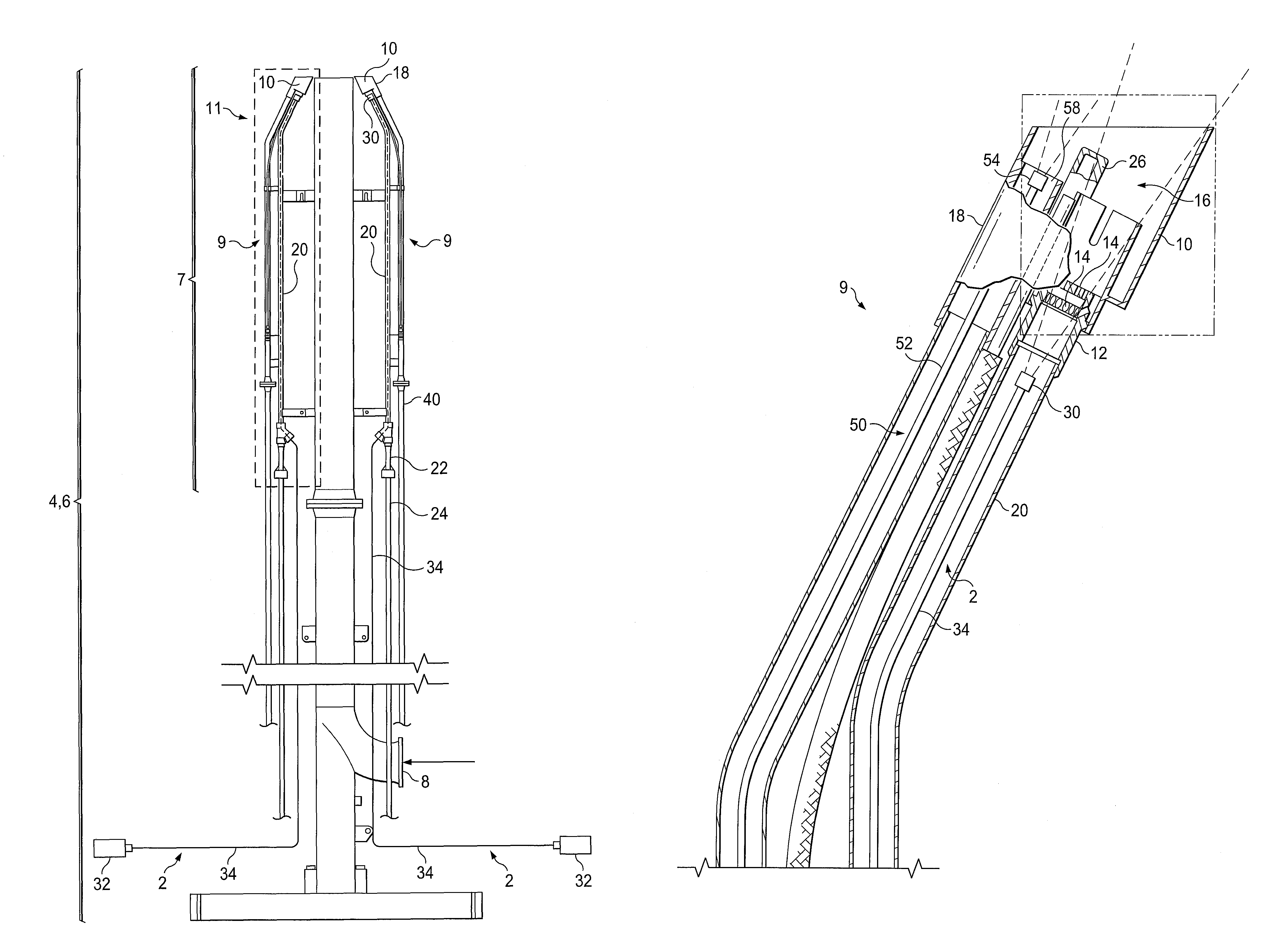
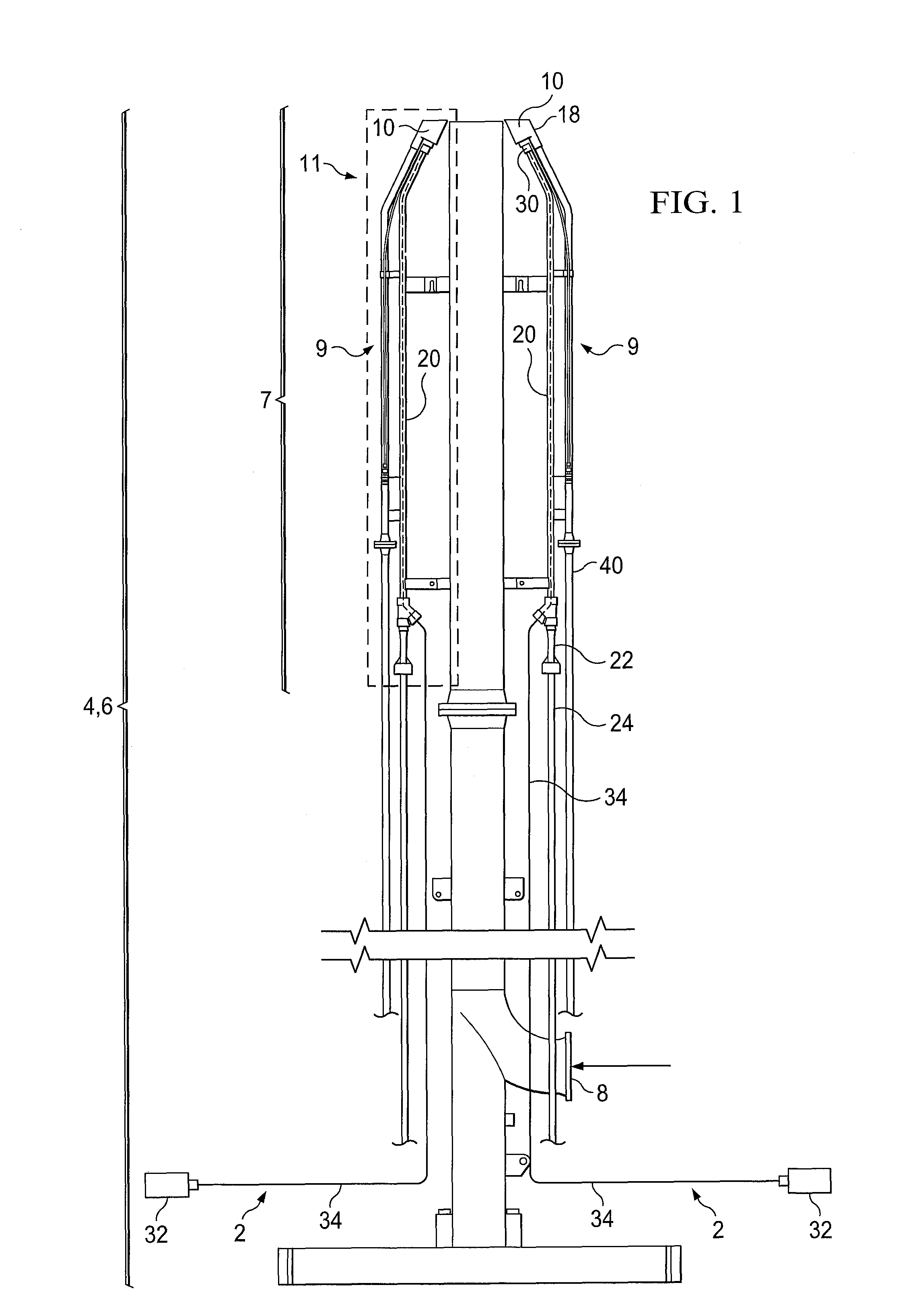
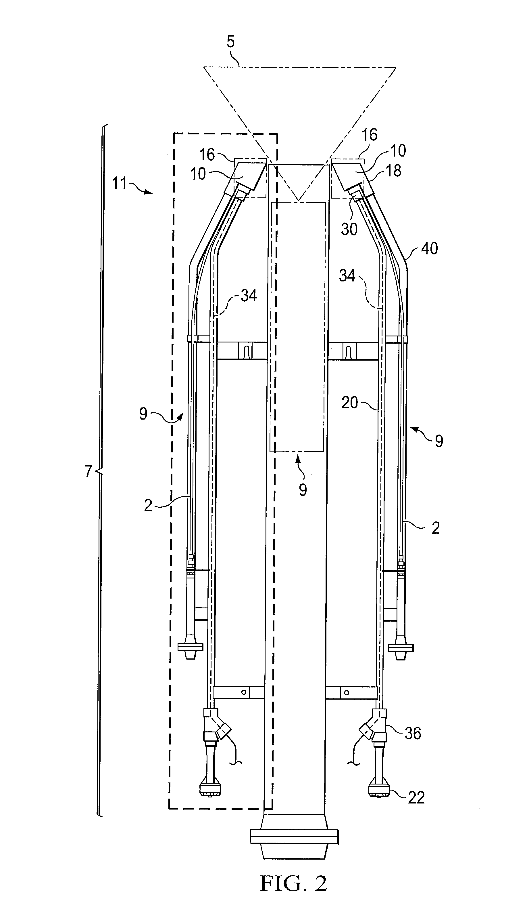
[0023]In FIGS. 1-4, embodiments 2 of the inventive monitoring apparatus are illustrated as installed in a flare stack system 4 for monitoring the flare pilot burners 10. The flare stack system 4 comprises: a vertical flare stack 6 which can typically be anywhere in the range of from about 15 ft to about 400 ft in height; a flare combustion zone 5 at the top 11 of the flare stack 6; a delivery line 8 which delivers waste gas or released gas to the flare stack 6 sporadically (e.g., as a result of ...


PUM


Abstract

An apparatus and method for monitoring the status of one or more pilot flames or of the main flame in a flare system. A collimator, quartz light tube, or other receiver is positioned near the combustion zone and receives an image which is transmitted via a fiber optic line to an analyzing sensor which is located at a safe distance from the flare system. The fiber optic line preferably extends through a pilot gas line, a flame front generator line, or other protective conduit so that the fiber optic line can be cooled and purged by pilot gas, instrument air, or other cooling gas media which is continuously delivered through the conduit.

Description

FIELD OF THE INVENTION[0001]The present invention relates to apparatuses and methods for monitoring flare pilot burners and for monitoring flare systems.BACKGROUND OF THE INVENTION[0002]Process flare systems are widely used in the refining, chemical, petrochemical, petroleum production, and other industries for burning flammable and / or toxic materials which are released due to upset or startup conditions, or which are released simply as a result of the process itself. Flare stacks and other flare systems typically include one or more flare pilot burners which must remain in continuous operation in order to ignite the materials which are disposed of through the flare system.[0003]A need exists for an apparatus and method for monitoring process flares and flare pilot burners which (a) provide reliable, instantaneous feedback, (b) are capable of identifying and monitoring each individual pilot burner in the flare system, as well as the flare itself, and (c) can be repaired, maintained ...

Claims


Application Information

Patent Timeline
IPC IPC(8): F23N5/08F23N5/24
CPCF23G5/50F23G7/085F23N5/242
Inventor LITTLE, CODY L.JONES, KYLE D.SMITH, SCOT K.BEATS, ANDREWFRANCIS, CLAYTONLEE, ERIN
Owner ZEECO
Learn More