Energy storage systems and methods

a technology of energy storage and energy storage cells, applied in the direction of battery/fuel cell control arrangement, emergency power supply arrangement, capacitor propulsion, etc., can solve the problems of not being able to achieve chemical reactions instantaneously, not nearly as good system performance over the full range of actual loads, etc., to achieve better and more sophisticated improve the control of the energy storage system, and improve the effect of battery li

Active Publication Date: 2016-03-01
UCAP POWER INC
View PDF23 Cites 11 Cited by
  • Summary
  • Abstract
  • Description
  • Claims
  • Application Information

AI Technical Summary

Benefits of technology

[0021]In an energy storage system that includes a battery and an ultracapacitor, the state of charge (SOC) of the capacitor is the subject of a dynamic set-point. This dynamic set-point control is a function of the load regime to which the storage system is exposed, for example a hybrid automobile or electric automobile. The control may be based in part upon real-time fast Fourier transform analysis of load current, permitting real-time adjustment of control coefficients. In this way, it is possible to minimize the occurrence of the capacitor being fully charged at a time when it would be desired to be able to absorb high current, for example from regenerative braking. Likewise it is possible to minimize the occurrence of the capacitor being nearly discharged at a time when it would be desirable to have boost power available. A result is that even a relatively small ultracapacitor (having perhaps one two-hundredth the energy storage capacity of the battery) can permit greatly reducing waste heat dissipated in the battery, and can reduce otherwise unnecessary cycling of current into and out of the battery. This can extend battery life and battery performance.

Problems solved by technology

But present-day systems, even those that employ both an ultracapacitor and a battery, leave much room for improvement.
The system performance is not nearly as good over the full range of actual loads and service use.
The chemical reactions cannot happen instantly but take some time.
This means that the battery cannot deliver all or part of its stored energy instantly, but takes some time to deliver its energy.
This likewise means that if energy enters the storage system from outside (for example due to regenerative braking), such energy cannot be instantly stored to the battery but takes some time to do so.
Efforts to draw large amounts of energy very quickly from the battery can lead to heating which offers several drawbacks—first, the heating represents a waste of energy that could otherwise have been put to some good use, second, the heating represents a need to design a mechanism for dissipating the heat from the battery, and third, the heating can reduce the service life and can increase the risk of premature failure.

Method used


Image

  • Energy storage systems and methods
  • Energy storage systems and methods
  • Energy storage systems and methods

Examples


Embodiment Construction

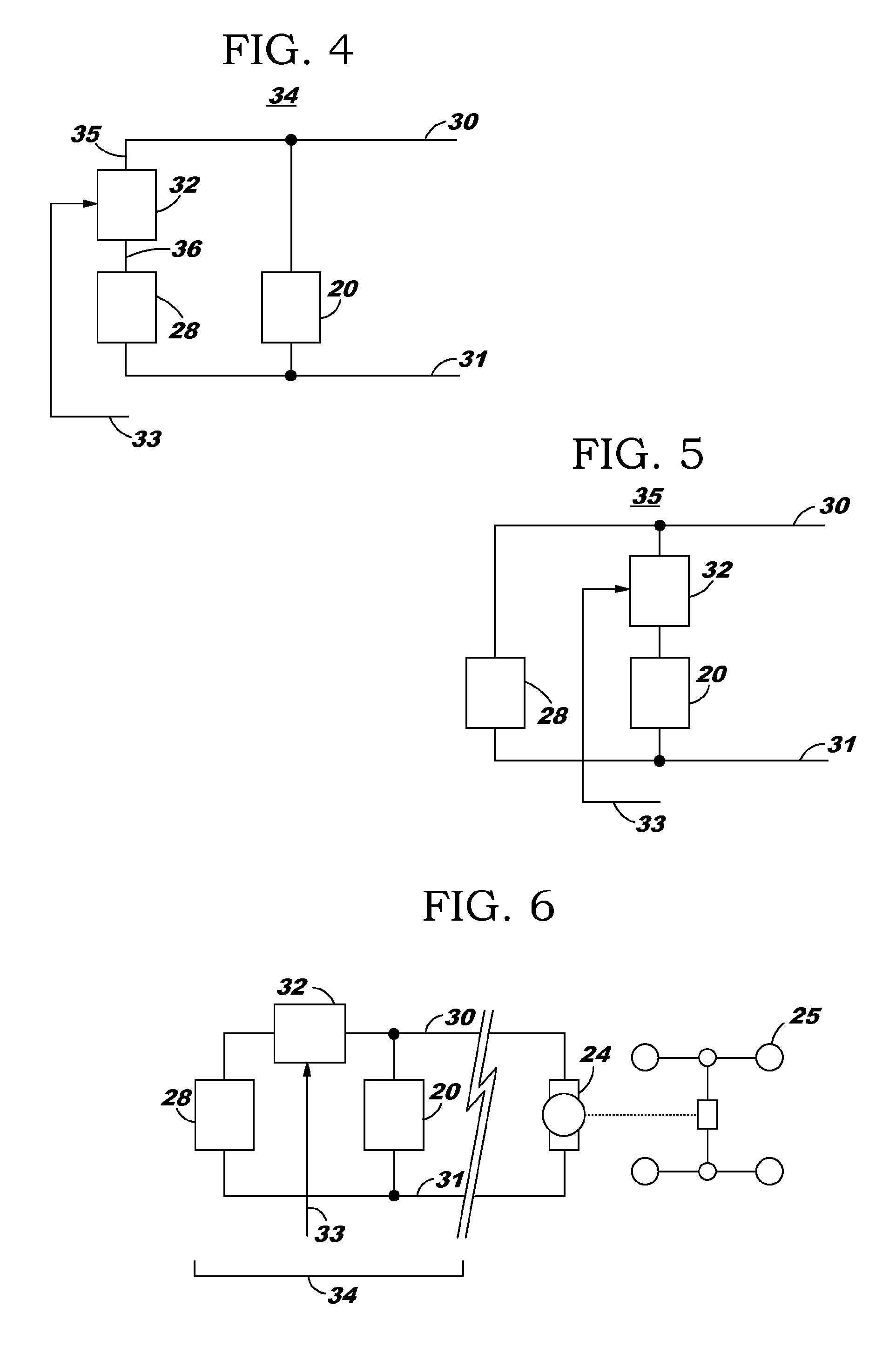
[0037]To more fully appreciate the invention, it is helpful to describe some of the current flows that might happen in operation of the automobile of FIG. 6.

[0038]In the event of a heavy load (for example if the automobile is going uphill, or if the operator is pressing the accelerator pedal, or both), then motor 24 may draw current 37 from the ultracapacitor 28 and may draw current 36 from the battery 20, as shown in FIG. 7. Kirchhoff's law would, of course, be satisfied, so that the current through terminal 30 (and thus through terminal 31) will be the sum of the two currents just mentioned.

[0039]FIG. 8, in contrast, shows the system of FIG. 6 with current flowing from the motor-generator toward the energy storage system. For example the operator of the automobile may be pushing hard on the brake, which causes the motor-generator 24 to become a generator, giving rise to regenerative braking. In such a case there may be a current 41 flowing into the capacitor 28 and a current 40 fl...


PUM


Abstract

In an energy storage system that includes a battery and an ultracapacitor, the state of charge (SOC) of the capacitor is the subject of a dynamic set-point. This dynamic set-point control is a function of the load regime to which the storage system is exposed, for example a hybrid automobile or electric automobile. The control may be based in part upon real-time fast Fourier transform analysis of load current, permitting real-time adjustment of control coefficients. In this way, it is possible to minimize the occurrence of the capacitor being fully charged at a time when it would be desired to be able to absorb high current, for example from regenerative braking. Likewise it is possible to minimize the occurrence of the capacitor being nearly discharged at a time when it would be desirable to have boost power available. A result is that even a relatively small ultracapacitor (having perhaps one two-hundredth the energy storage capacity of the battery) can permit greatly reducing waste heat dissipated in the battery, and can reduce otherwise unnecessary cycling of current into and out of the battery. This can extend battery life and battery performance.

Description

[0001]This patent application claims the benefit of U.S. patent application Nos. 61 / 298,204 and 61 / 298,206, each filed Jan. 25, 2010, each of which is hereby incorporated herein by reference for all purposes.BACKGROUND[0002]In many high-power systems, the combination of an ultracapacitor and a battery works much better than the battery by itself. But present-day systems, even those that employ both an ultracapacitor and a battery, leave much room for improvement. The system performance is not nearly as good over the full range of actual loads and service use. And the battery does not last as long as one might wish. As will be explained in great detail below, the invention offers better performance and an expectation of longer battery life. But first, some background will be provided which may establish some terminology and which may help in an appreciation of the great needs that were until now unfulfilled.[0003]FIG. 1 shows a simplified block diagram of a hybrid automobile 21. An i...

Claims


Application Information

Patent Timeline
Patent Type & Authority Patents(United States)
IPC IPC(8): H02J7/34B60L11/00B60L3/00B60L11/18B60L1/00
CPCB60L11/005B60L3/0046B60L11/1803B60L11/1861B60L2240/36B60L2250/22Y02T10/705Y02T10/7005Y02T10/7022Y02T10/7044Y10T307/625B60L50/40B60L50/51B60L58/13B60L58/18B60L58/25Y02T10/70Y02T10/7072Y02T90/14B60L2210/10B60Y2200/91B60Y2200/92B60L50/60B60L53/24B60L58/12
Inventor MILLER, JOHN, M.
Owner UCAP POWER INC
Why Eureka
Try Eureka