Enhanced RF location methods and systems

a technology of location method and rf, applied in the direction of direction finders, direction finders using radio waves, instruments, etc., can solve the problems of multi-path signal contamination of the use of the known locator system, insufficient signal strength, and hinder the use of electronic locating systems in indoor environments. , to achieve the effect of increasing the accuracy

Inactive Publication Date: 2016-03-01
WORCESTER POLYTECHNIC INSTITUTE
View PDF5 Cites 0 Cited by
  • Summary
  • Abstract
  • Description
  • Claims
  • Application Information

AI Technical Summary

Benefits of technology

[0007]Inertial tracking is possible in some situations, in which linear accelerations and rotational velocities of an inertial measurement unit are computationally integrated to obtain a relative position track. However, inertial position estimates are the outcome of a double time integral, which causes their error (due to measurement unit errors such as bias and scale error and timewise drift of these errors) to grow with time as t2, while rotational error, similarly due to a single integration, grows as t. These problems can be mitigated to some extent by use of very low bias error devices but at typically hugely increased monetary cost, increased size and increased power consumption. Furthermore, as inertial tracking solutions are relative in nature (both in position and rotation), accurate initialization of orientation and position are necessary to track absolute position. This kind of initialization can be difficult to impossible to conduct in some situations or in a sufficiently timely fashion to be practicable, such as in applications involving first responders at an emergency.
[0009]Methods and systems that use the time-wise stability of RF location systems and the short time relative position displacement accuracy and spatial stability of inertial tracking system to increase the accuracy of a combined tracking method and system are presented hereinbelow.
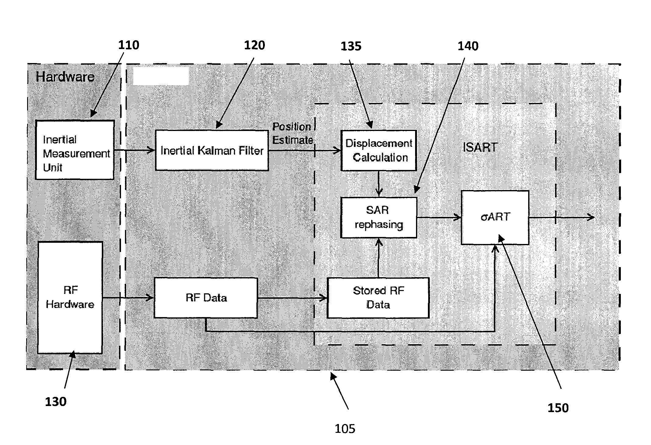
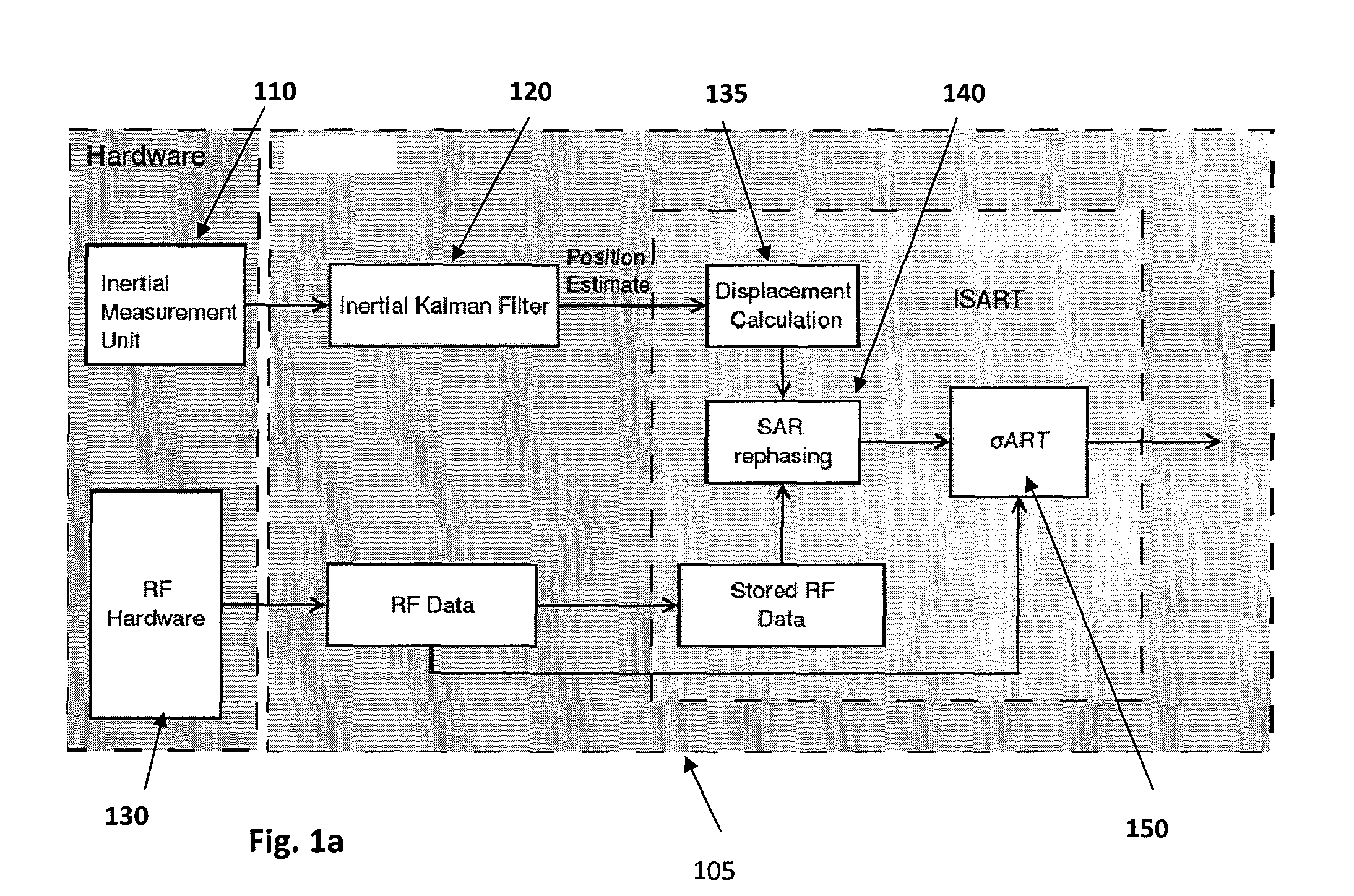
[0010]In one or more embodiments, the method of these teachings includes determining relative displacements between a location of a mobile node at each of two or more data captures, the mobile node exchanging RF signals with a number of reference nodes, re-phasing the RF signals to a virtual node location; constituting re-phased RF data and providing the RF data and the re-phased RF data to an RF location component, wherein effective signal-to-noise ratio and hence position estimation accuracy from the RF information are increased beyond what would be achievable with only the RF information. The advantage of combining the short-term relative motion information with RF information can also be interpreted as providing solutions consistent with high performance inertial devices with smaller, lower cost devices.

Problems solved by technology

However, in the past, several factors have hindered the use of known electronic locating systems in indoor environments.
One major impediment to the use of known locator systems is multi-path signal contamination, referring to the signal scattering effect caused by the local environment between the transmitter and the receiver, such as walls, support beams and furnishings.
Other impediments include insufficient signal strength, lack of precision, the FCC spectrum non-compliance of ultra wide band systems, the need for pre-existing infrastructure, and failure of simple pulse distortion models in actual through-building and multi-path propagation conditions.
Methods for mitigating the impact of “multi-path” components have been disclosed but may be insufficient in the face of severe multi-path conditions.
Additionally, the reference node antenna constellation is often limited by practical considerations, which can often result in a severe geometric dilution of precision.
However, inertial position estimates are the outcome of a double time integral, which causes their error (due to measurement unit errors such as bias and scale error and timewise drift of these errors) to grow with time as t2, while rotational error, similarly due to a single integration, grows as t. These problems can be mitigated to some extent by use of very low bias error devices but at typically hugely increased monetary cost, increased size and increased power consumption.
This kind of initialization can be difficult to impossible to conduct in some situations or in a sufficiently timely fashion to be practicable, such as in applications involving first responders at an emergency.

Method used


Image

  • Enhanced RF location methods and systems
  • Enhanced RF location methods and systems
  • Enhanced RF location methods and systems

Examples


Embodiment Construction

[0023]The following detailed description is of the best currently contemplated modes of carrying out these teachings. The description is not to be taken in a limiting sense, but is made merely for the purpose of illustrating the general principles of these teachings, since the scope of these teachings is best defined by the appended claims.

[0024]The present teachings will be more completely understood through the following description, which should be read in conjunction with the drawings. In this description, like numbers refer to similar elements within various embodiments of the present disclosure. Within this description, the claims will be explained with respect to embodiments. The skilled artisan will readily appreciate that the methods, apparatus and systems described herein are merely exemplary and that variations can be made without departing from the spirit and scope of the disclosure.

[0025]As used herein, the singular forms “a,”“an,” and “the” include the plural reference...


PUM


Abstract

Methods and systems that use the time-wise stability of RF location systems and the short time accuracy and spatial stability of inertial tracking system to increase the accuracy of tracking method.

Description

CROSS REFERENCE TO RELATED APPLICATIONS[0001]This application claims priority to U.S. Provisional Application Ser. No. 61 / 502,672, filed Jun. 29, 2011, entitled ISART EXTENSION OF THE SART, which is incorporated by reference herein in its entirety and for all purposes.STATEMENT REGARDING FEDERALLY SPONSORED RESEARCH OR DEVELOPMENT[0002]This invention was made partially with U.S. Government support from the Department of Homeland Security under grant No. NNG09CP11C. The U.S. Government has certain rights in the invention.BACKGROUND[0003]These teachings relate to locating objects by use of combined methods.[0004]The precise tracking of persons and / or objects is desirable in many applications. One way to achieve precision indoor location with electronic tracking systems is by ranging (estimating the distance) between one or more base stations and a mobile locator device. Known examples of electronic locating systems that perform ranging are GPS technology, in which satellite transmissi...

Claims


Application Information

Patent Timeline
Patent Type & Authority Patents(United States)
IPC IPC(8): G01S3/02G01S5/02
CPCG01S5/021G01S5/0257G01S5/0294G01S5/0252G01S5/02585
Inventor CYGANSKI, DAVIDDUCKWORTH, R., JAMES
Owner WORCESTER POLYTECHNIC INSTITUTE
Why Eureka
Try Eureka