
Code profiling in embedded ULE applications

a technology of embedded ule and code profiling, applied in the direction of specific program execution arrangements, instruments, electric digital data processing, etc., can solve the problems of code profiling not being performed for these devices so far, requiring too much chip area and thus too expensive, and not being able to provide trace units. , to achieve the effect of short wake-up tim

Active Publication Date: 2016-03-01
DIALOG SEMICONDUCTOR BV
View PDF38 Cites 2 Cited by
  • Summary
  • Abstract
  • Description
  • Claims
  • Application Information

AI Technical Summary

Benefits of technology

The present disclosure aims to optimize software of standalone devices with short wakeup time compared to sleep-time. It specifically targets devices with low energy requirements and short standby time. Code profiling is achieved without the need for a trace unit or an external PC, which helps extend the device's standby time and achieve low-energy efficiency. The overall objective is to enable effective code profiling at minimal cost.

Problems solved by technology

But for most of the ultra-low energy (ULE) devices (e.g. DECT and Bluetooth Low Energy devices or other devices having a low duty cycle) such a Trace unit is not available.
Such a Trace unit on chip requires too much chip area and is hence too expensive.
Therefore code profiling cannot be performed for these devices so far.
Also if this trace unit would be available it would be impossible to do this Code Profiling for an ULE device (or other devices having a low duty cycle), because this device is going to sleep mode for e.g. 20 seconds and wakeups for only e.g. 20 Milliseconds.
This wake up time is too short for a debugger to set up its conversation with this ULE device and so the debugger can't use the trace functionality for doing his Code profiling.
Code profiling by setting port pins would also not be always possible because the ULE devices have only a limited amount of output pins.
Therefore code profiling cannot be performed for devices having a short wakeup mode and therefore the code cannot be optimized these days.
This could result in too long time spent in wakeup mode.
Finally this relative long wake up time results in a shorter standby time of the ULE device.

Method used

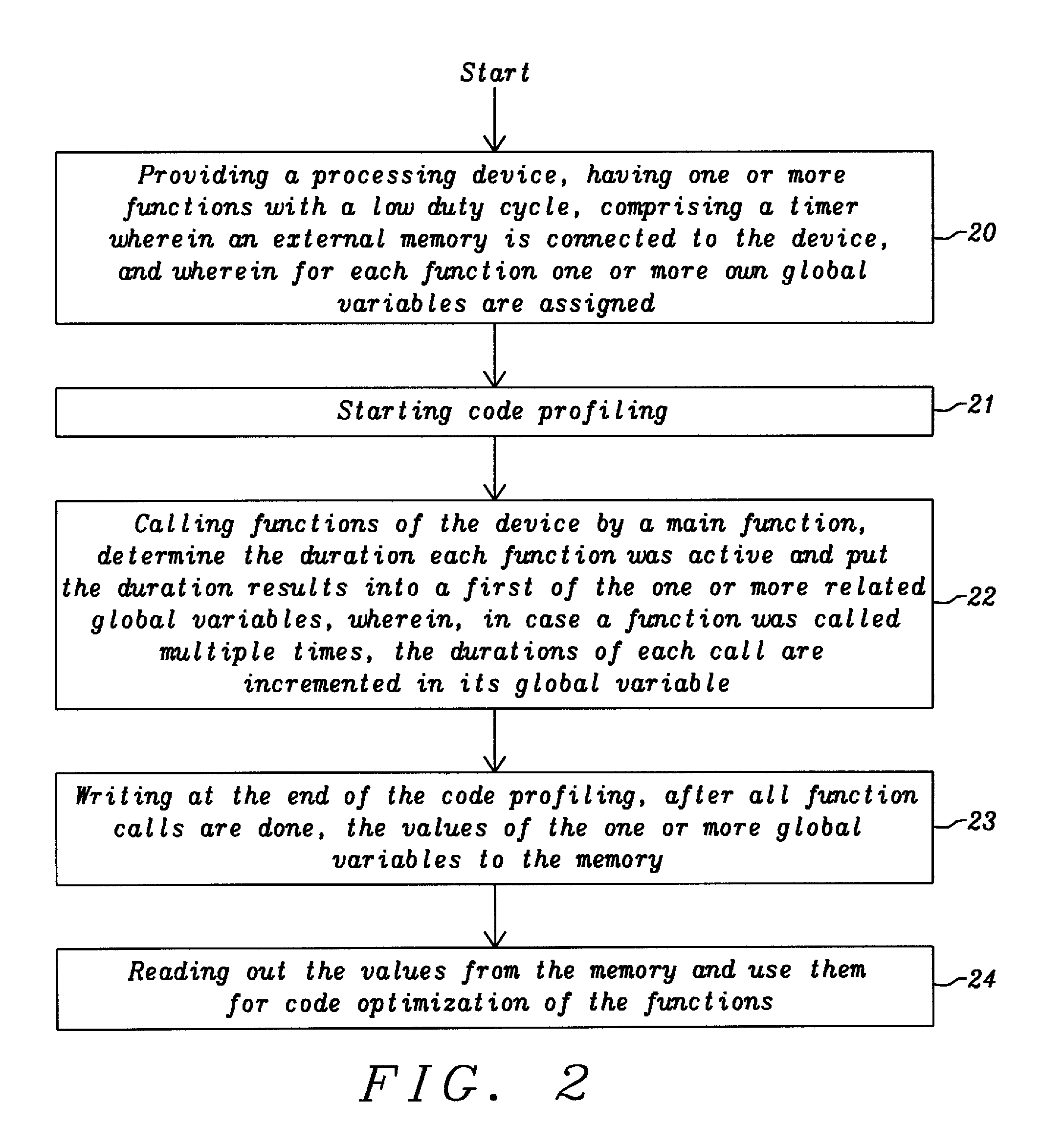

Image

  • Code profiling in embedded ULE applications
  • Code profiling in embedded ULE applications
  • Code profiling in embedded ULE applications

Examples


Embodiment Construction

[0023]The preferred embodiments of the present disclosure disclose how to perform code profiling on devices having a relatively short wake-up time compared to the sleep time (low duty cycle).

[0024]A preferred embodiment of the disclosure performs code profiling on an ultra-low energy (ULE) device. The disclosure can be applied to any other devices having low duty-cycle.

[0025]The range of duty cycle, i.e. the ratio between wake-up time / sleep-time may be e.g. approximately 1 / 1000. This means x mseconds wake-up time and x seconds sleep-time. The disclosure could be also advantageously be applied to other ratios

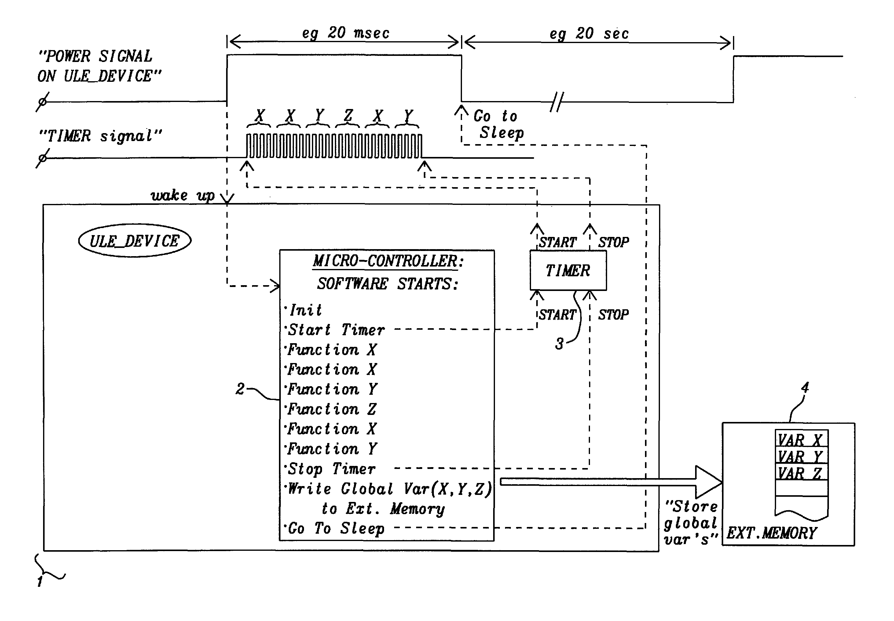
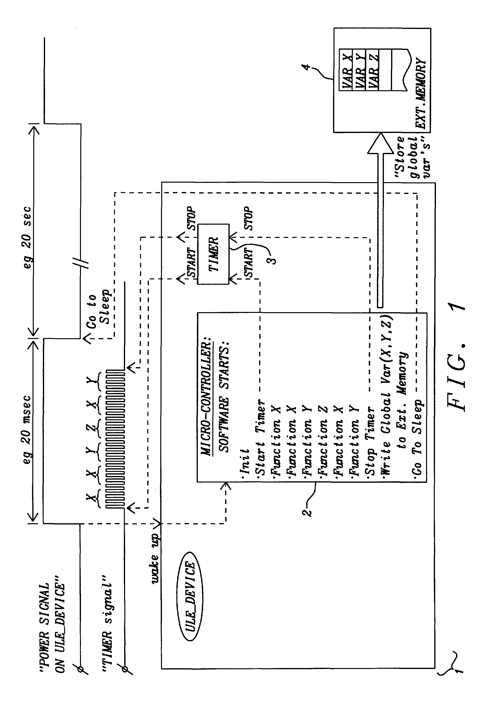
[0026]FIG. 1 shows a block diagram of an ULE device 1 including its micro-controller 2, Timer 3, and an external memory 4.

[0027]The code profiling method disclosed uses an available timer 3 on the ULE device (this may be a system timer (Systick) or another on-chip timer). The value of global variables is stored in an (e.g. external) non-volatile memory 4 (e.g. EPROM) before the d...


PUM


Abstract

Mobile electronic devices and related methods to achieve an enhanced security level are disclosed. A security module is deeply embedded in a non-open companion chip of the mobile device, wherein the companion chip controls vital functions of the mobile device. Any security technology can be provided by the security module. The security module can, in case of a security violation, disable all vital functions of the companion chip without requiring communicating to other components of the mobile device. The vital functions deployed in the companion chip comprise e.g. system power management or audio functions.

Description

BACKGROUND[0001](1) Field of the Disclosure[0002]This disclosure relates generally to the field of analysis of computer program code and relates in particular to code profiling on stand-alone devices.[0003](2) Description of the Background[0004]For optimizing software in Microcontrollers it is necessary to debug this software by using Profiling. Code profiling is measuring relatively the number each function is called and its duration. So, if a function A is e.g. 30% of the time active it would be useful for the software engineer to optimize the code in this function. If function B is e.g. 0.05% of the time active, it may be not be necessary to optimize it.[0005]This Code profiling could be performed for several processors, e.g. ARM (a reduced instruction set computer (RISC) instruction set architecture (ISA) developed by ARM Holdings) processors, by a Trace Unit or another debug unit. Debugger software running on a PC use this embedded Trace Unit to do the code profiling and the re...

Claims


Application Information

Patent Timeline
Patent Type & Authority Patents(United States)
IPC IPC(8): G06F9/44G06F11/34G06F1/32
CPCG06F11/3419G06F1/3203G06F2201/865
Inventor ROOVERS, WIK
Owner DIALOG SEMICONDUCTOR BV
Learn More