Oil—water separator

a technology of oil and water separator, which is applied in the direction of water cleaning, separation process, chemical apparatus and process, etc., can solve the problems of slowing down the ascent speed of oil droplets in the left limb, undesirable shear, etc., and achieves relatively rapid and efficient separation, reduce the formation of emulsions, and facilitate separation. rapid and easy

Active Publication Date: 2016-03-15
BOARD OF SUPERVISORS OF LOUISIANA STATE UNIV & AGRI & MECHANICAL COLLEGE
View PDF17 Cites 3 Cited by
  • Summary
  • Abstract
  • Description
  • Claims
  • Application Information

AI Technical Summary

Benefits of technology

[0010]I have discovered an oil-water separator that may be used to separate oil from water in situ, while deployed on the ocean or other body of water. Oil and water are separated in situ, rather than being collected in a tank or barge to be transported for later separation onshore. Separation is relatively rapid and efficient. Oil is lighter than water. This difference in density is exploited to cause the oil and water to separate between two limbs of the apparatus, and to collect the oil and water from two different ports. An “oil-out port” on one limb is higher than a “water-out port” on the other limb. Only oil, not water, will reach the level of the higher “oil-out port” against gravity, because of the differential densities of the two liquids. The oil-out port releases essentially oil and only oil, irrespective of the ratio at which oil and water enter the apparatus. The input may contain oil:water in essentially any ratio at which the two liquids are immiscible, from nearly all water with little oil, to nearly all oil with little water, or any ratio in between. The apparatus may be placed within a boat or ship, or it may be mounted on pontoons or other floatation gear and towed behind a boat or ship. A low-shear pump is employed to minimize the formation of emulsions as fluid is pumped into the apparatus. The dimensions and configuration of the limbs of the apparatus are preferably configured to make the apparatus stable when deployed in ocean waves.
[0011]In one embodiment, the novel separator comprises two principal limbs, which will sometimes be called the “left” limb and the “right” limb for convenience of reference. (There is nothing unique about the labels left and right per se. The two limbs could alternatively be called the first and second limbs, or the oil and water limbs, etc.) A mixture of water and oil, typically with entrained air bubbles as well, enters the separator through a port on the lower portion of the left limb. See FIG. 1. A gentle action, low-shear pump (such as an engine driven diaphragm pump, for example an Izumi Sludge Pump, Model #SMD-80HX, or a peristaltic pump, or another gentle action, positive displacement pump) pumps the oil-water (or oil-water-air) mixture into the device. By contrast, a “regular,” or centrifugal pump would typically turn an oil-water or oil-water-air mixture into an emulsion, which is undesirable because an emulsion can require hours or even days to re-separate. The pump preferably has self-priming capabilities, and can work over a range of ratios of oil, fresh water, salt water, and air. If oil and water are introduced without forming an emulsion, the separation may be made more rapidly and easily, without the need for expensive and energy-intensive centrifuges. The device is energy-efficient compared to other means available for oil-water separations. The low-shear pump should produce output having laminar flow, i.e., with a Reynolds number less than about 2,100.
[0012]Once the oil-water-air mixture enters the left chamber, the air floats to the surface relatively quickly. Due to the buoyancy of the air, most of the air can escape as bubbles through an optional inner tube within the left limb. However, a fraction of the air will not enter the inner tube but will instead reach the top surface of the liquid by bubbling through the space between the inner tube and outer wall of the left limb. The fraction of air passing between the inner tube and the outer wall of the left limb is preferably small enough that it induces no more than minimal turbulence in the floating oil layer, and does not substantially affect separator performance. An alternative option for air release is depicted in FIG. 2: In the alternative embodiment air in the inlet line is released before the oil-water mixture enters the main chamber of the separator, thereby minimizing turbulence in the left limb. Additionally, it is preferred to configure the intake to minimize the amount of air that is introduced into the system initially.
[0013]Because oil is lighter than water, the oil floats upward in the left limb. The pumping can not only induce flow of the liquids, it can also cause shear. Shear is undesirable because it tends to reduce the size of oil droplets, which in turn slows the velocity of the ascent of oil droplets in the left limb. It is therefore preferred to use a low shear pump. Additionally, it is preferred that the diameter of the left limb should be larger than that of the right limb, both to increase the hydraulic retention time in the left limb, and also to lower turbulence in the left limb.
[0014]Having a larger diameter in the left limb improves separation efficiency. The entrance of the device is the area that tends to have the highest turbulence. Thus reducing the velocity at the entrance can significantly enhance oil / water separation. It is preferred that the linear velocity of flow should not exceed about 15 inches (40 cm) per minute when separating mixtures of crude oil and sea water. This velocity may vary, depending on particular specific gravities, viscosities, and other physical or chemical properties. Using a low-shear pump helps reduce turbulence. Having a large diameter in the left limb also helps reduce turbulence. However, a larger diameter for the left limb also increases the overall weight of the device (both material weight and liquid weight). Some very fine oil droplets and emulsions may be carried along with the exiting water into the right chamber and through the water-out port; by minimizing turbulence, the amount of oil carried to the water-out port may be minimized.

Problems solved by technology

By contrast, a “regular,” or centrifugal pump would typically turn an oil-water or oil-water-air mixture into an emulsion, which is undesirable because an emulsion can require hours or even days to re-separate.
The pumping can not only induce flow of the liquids, it can also cause shear.
Shear is undesirable because it tends to reduce the size of oil droplets, which in turn slows the velocity of the ascent of oil droplets in the left limb.

Method used


Image

  • Oil—water separator
  • Oil—water separator
  • Oil—water separator

Examples


Embodiment Construction

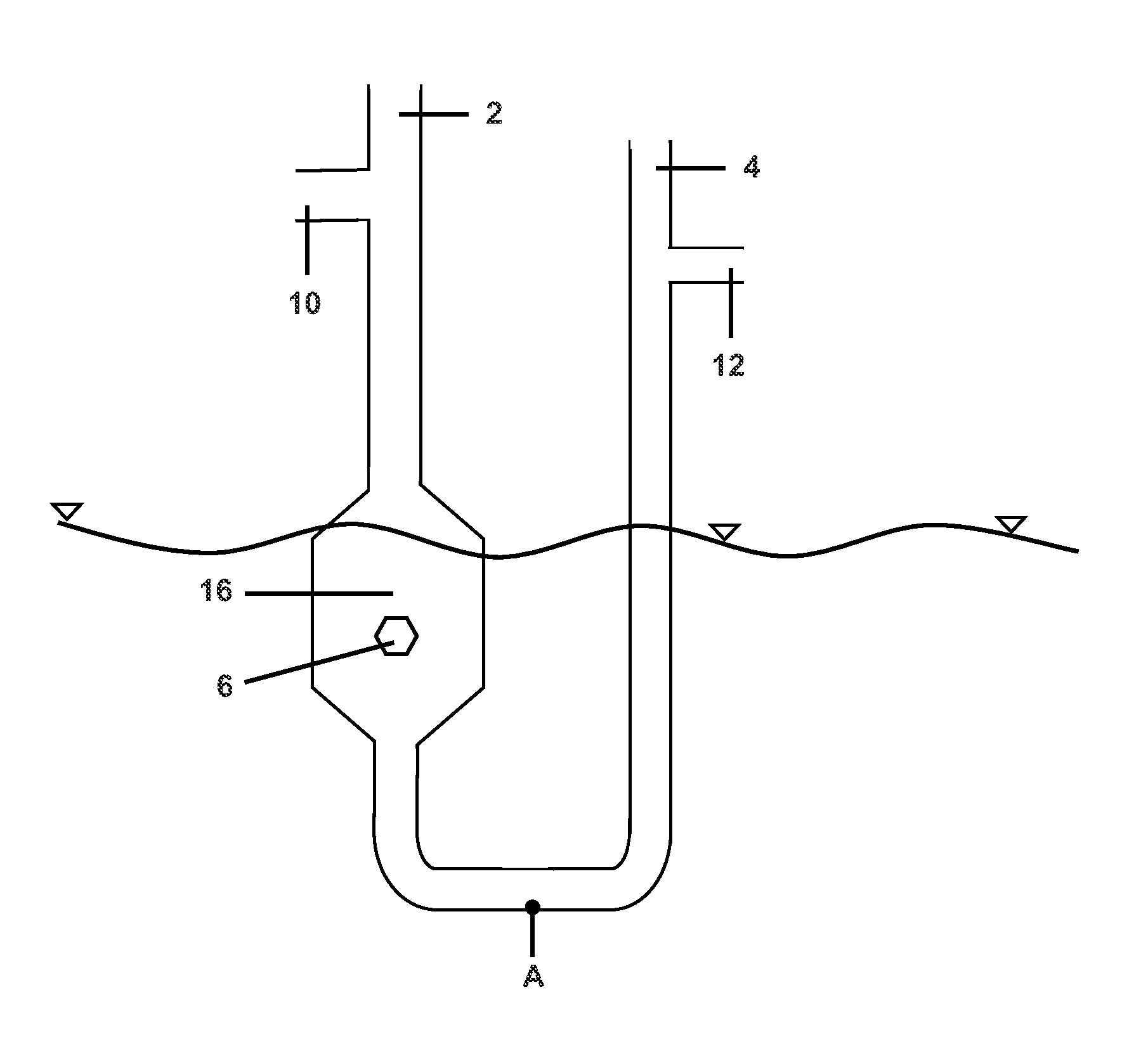
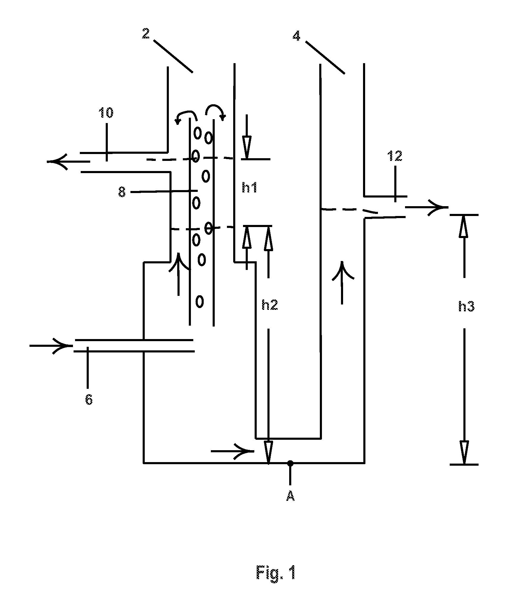
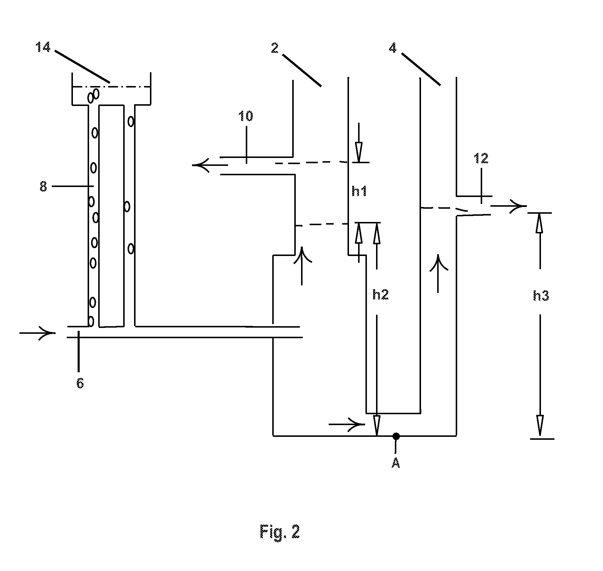
[0019]Looking for example at FIG. 1, in one embodiment a separator in accordance with the invention may be thought of as having a configuration generally as that of a large U tube. At the point marked “A,” the pressure from the left limb 2 (ρoil×g×h1+ρH2O-mostly×g×h2) equals the pressure from the right limb 4 (ρH2O×g×h3). The Greek letter ρ denotes the density of the particular fluid. The density of oil is less than the density of water (whether fresh or salt water). The invention exploits this difference in density to separate the oil and water between the two limbs 2 and 4, and to collect the oil and the water from two different ports, 10 and 12, respectively. The oil-out port 10 on the left limb 2 is higher than the water-out port 12 on the right limb 4. Therefore, oil exits the oil-out port 10 only when the height of the oil layer in the left limb (h1) is sufficient to reach the oil-out port 10. Air or other gases in the intake may escape as bubbles through an optional inner tub...


PUM

PropertyMeasurementUnit
Reynolds numberaaaaaaaaaa
heightaaaaaaaaaa

Abstract

A separator is disclosed that may be used to separate oil from water in situ in the ocean or other water body. The difference in density between oil and water causes them to separate between two limbs of the apparatus, and to exit from different ports at different heights. The input may contain oil:water in essentially any ratio. The apparatus may be placed within a boat or ship, or it may be mounted on pontoons or other floatation gear and towed behind a boat or ship.

Description

[0001]This is the United States national stage of international application PCT / US2011 / 037880, international filing date May 25, 2011, which claims the benefit of the May 28, 2010 filing date of U.S. provisional patent application Ser. No. 61 / 349,329 under 35 U.S.C. §119(e).TECHNICAL FIELD[0002]This invention pertains to an apparatus and method for separating immiscible liquids, particularly to an apparatus and method for separating oil and water with an apparatus that is adapted to operate on the waves in situ, for example in remediating an oil spill.BACKGROUND ART[0003]During the catastrophic 2010 Gulf of Mexico oil spill, an estimated 600,000 gallons (2,300,000 liters) of sub-sea chemical dispersants were deployed. The long term effects of these dispersants are not known. Attempts were also made to skim oil at the surface, but only small amounts were actually recovered this way. There is an unfilled need for improved techniques to recover oil that has been spilled in the ocean or...

Claims


Application Information

Patent Timeline
Patent Type & Authority Patents(United States)
IPC IPC(8): E02B15/04C02F1/40B01D17/02C02F1/48B01D17/025C02F101/32
CPCE02B15/048B01D17/0208B01D17/0214C02F1/40C02F1/48C02F2101/32C02F2101/325
Inventor THEEGALA, CHANDRA, S.
Owner BOARD OF SUPERVISORS OF LOUISIANA STATE UNIV & AGRI & MECHANICAL COLLEGE
Why Eureka
Try Eureka