Integrated electronic sight and method for calibrating the reticle thereof

Active Publication Date: 2016-03-15
HUNTERCRAFT
View PDF6 Cites 20 Cited by
  • Summary
  • Abstract
  • Description
  • Claims
  • Application Information

AI Technical Summary

Benefits of technology

[0007]In the light of the above-mentioned technical problems, the present invention discloses a highly integrated electronic sight and method for calibrating the reticle comprising simulative calibration step, initial calibration step and pre-shooting calibration step. Initial calibration is performed based on the cal

Problems solved by technology

After long-term use, either the knob or other mechanical parts will be worn, resulting in error.
However, long-range shooting demands high-level of aiming accuracy.
A slight sight error will cause great variation on shooting results.
The shortcoming is extremely inconvenient in practical applications.
However, the increasing brightness from background to targeted object leads to decreased distinction in brightness between the boundary of targeted object image and background.
They have to rely on their own experience to determ

Method used


Image

  • Integrated electronic sight and method for calibrating the reticle thereof
  • Integrated electronic sight and method for calibrating the reticle thereof
  • Integrated electronic sight and method for calibrating the reticle thereof

Examples


Embodiment Construction

[0054]The objective, technical solutions and advantages of the present invention will be more apparent by describing in detail exemplary embodiments thereof with reference to the figures. It should be understood that the specific embodiments described herein are only intended to illustrate the present invention and are not intended to limit the present invention.

[0055]The present invention includes within its scope all embodiments defined by the appended claims including alternatives, modifications, equivalent method and solutions. Further, for clearer understanding the present invention, specific details are described below.

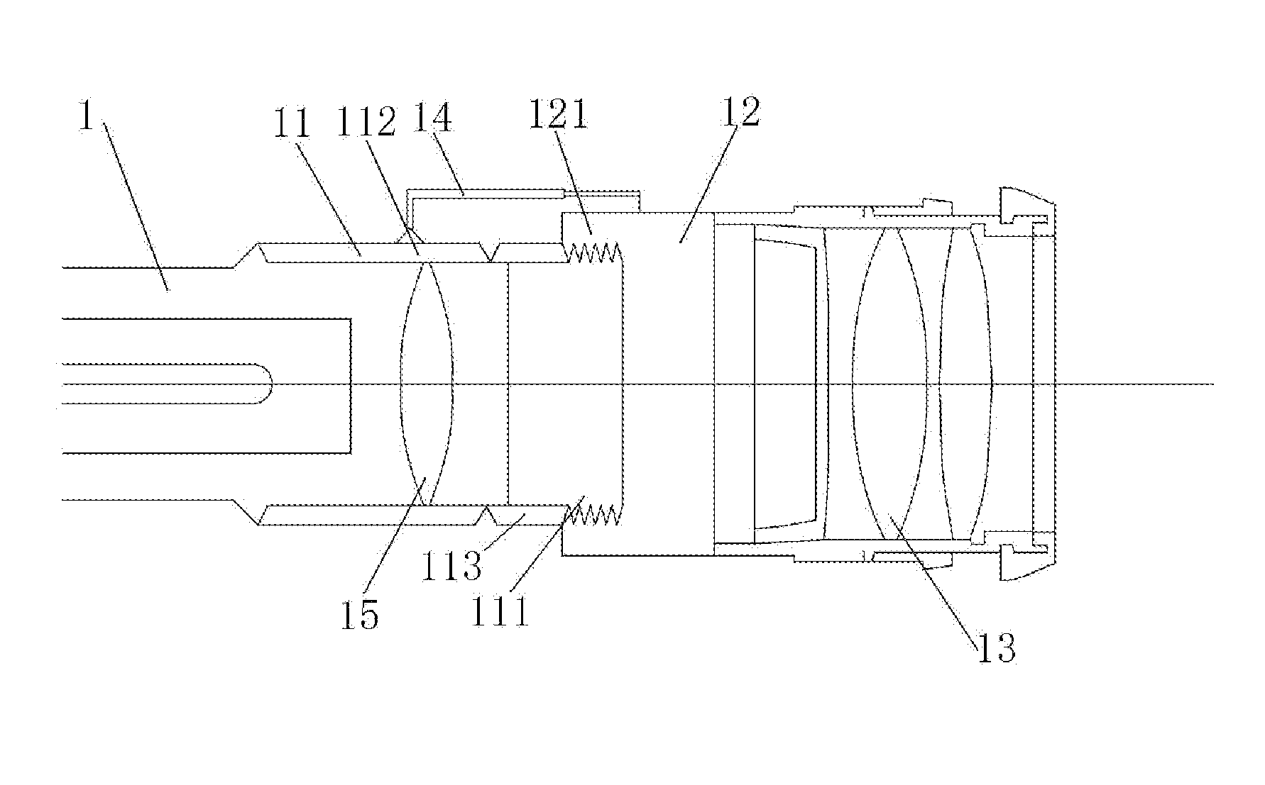
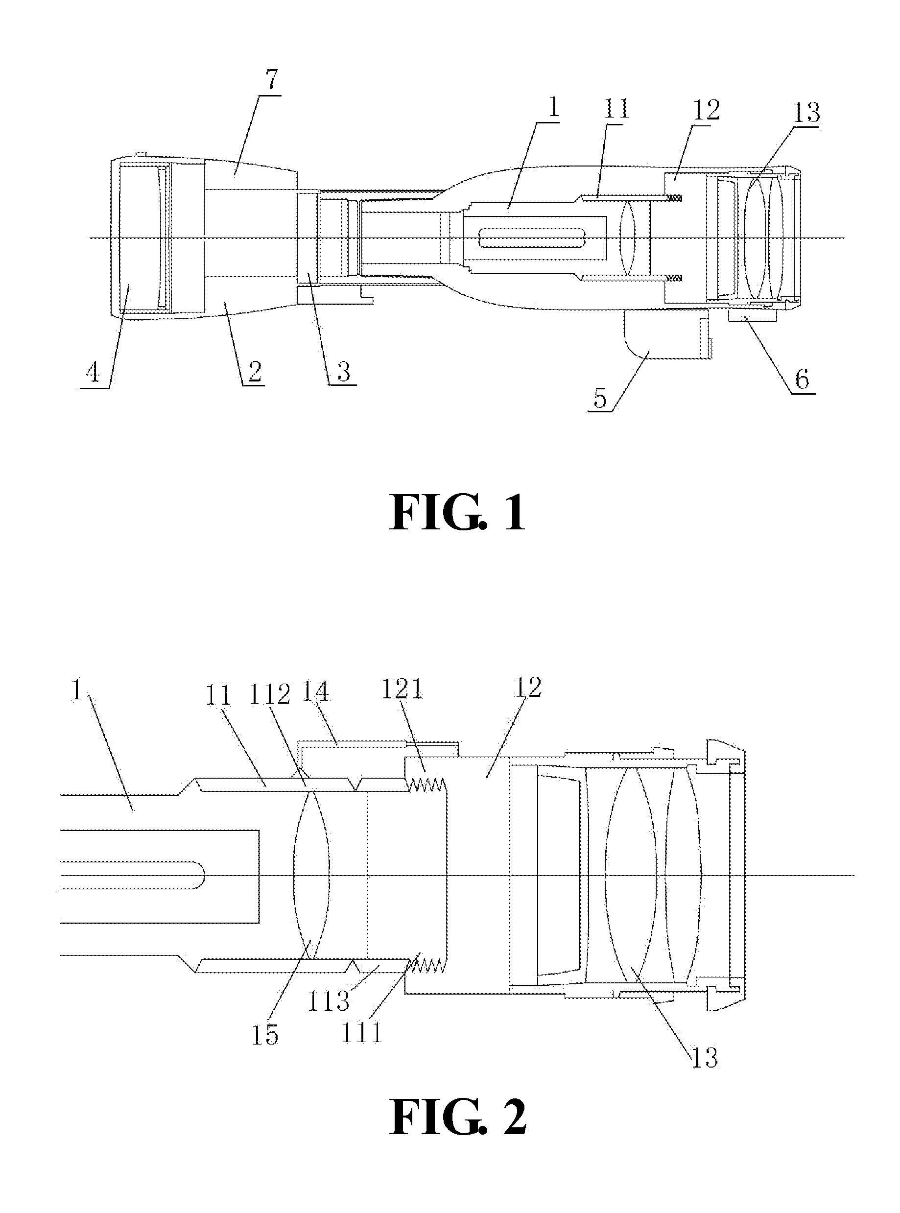
[0056]FIG. 1 shows a schematic view of an electric sight comprising a lens assembly 1, an image sensor 3, a processor 2, a memory, a touch screen display 4, an information acquisition device, a night vision device 6, a laser ranging device, a video recorder 5 and a Global Positioning System (GPS). The lens assembly 1 and night vision device 6 are connected to th...


PUM


Abstract

The present disclosure provides an electronic sight comprising a lens assembly, an image sensor, a processor, a memory, a touch screen, an information acquisition device, a night vision device, a laser ranging device, a video recorder and a Global Positioning System (GPS). The disclosure also provides a method for calibrating the reticle. A plurality of devices are highly integrated on the electronic sight to achieve a plurality of different functions including automatic adjusting magnification, night vision, providing optimal shooting image and laser ranging. The calibration method disclosed in the present invention comprises simulative calibration and pre-shooting calibration, which avoids wasting bullets in a situation that the point of impact cannot be identified after first shot. Reticles can be adjusted in real-time, achieving the same technical effect as non-polar reticles.

Description

FIELD OF INVENTION[0001]The present invention relates to the field of target shooting, and in particular an electronic sight and method for calibrating the reticle.BACKGROUND OF INVENTION[0002]Traditional sights include mechanical sights and optical sights. The mechanical sight refers to the metal sight, comprising a rear sight, a front sight and a notch, to assist aiming. The optical sight produces images using optical lens, with the target image and the line of sight superimposed on a same focal plane. Slight eye offset does not affect the aiming point.[0003]In the shooting process, both two traditional sights need to calibrate the reticle and the point of impact repeatedly, so that the point of impact and the reticle center coincide with each other, which requires repeatedly adjusting the knob, or other mechanical parts. After long-term use, either the knob or other mechanical parts will be worn, resulting in error. However, long-range shooting demands high-level of aiming accura...

Claims


Application Information

Patent Timeline
IPC IPC(8): F41G1/00F41G3/06F41G1/54
CPCF41G1/54F41G3/06F41G1/32F41G3/142F41G3/165F41G3/323
Inventor ZHANG, LINSHI, CHUNHUASU, SANG
Owner HUNTERCRAFT
Why Eureka
Try Eureka