Electric parking brake driving device and electric parking brake device

a technology of electric brakes and driving devices, which is applied in the direction of brake types, mechanical devices, brakes, etc., can solve the problems of belt slipping, transmission of driving force from electric motors may create problems, and the belt may be short or too long, and achieve compact size and low cost

Active Publication Date: 2016-03-29
ADVICS CO LTD
View PDF20 Cites 9 Cited by
  • Summary
  • Abstract
  • Description
  • Claims
  • Application Information

AI Technical Summary

Benefits of technology

[0016]According to the electric parking brake driving device according to the first aspect, the first rotating shaft is supported by the first bearing portion provided at the gear body and no spacer or the like is needed for supporting the first rotating shaft to the electric motor. This structure can avoid oversizing of the reduction gear mechanism, which leads to manufacturing of a cost reduced electric parking brake driving device. Further, since the gear reduction mechanism includes a drive gear fixed to the output shaft of the electric motor and a first driven gear having the number of teeth being more than the number of teeth of the drive gear and engaging with the drive gear, no transmitting mechanism with belt is needed for transmitting the rotation torque from the electric motor to the rotating member by reduction of rotation speed. Further, even if the position of the first rotating shaft relative to the electric motor is deviated, the driving force from the electric motor can be surely transmitted to be able to reliably park the vehicle without any problem.
[0017]According to the electric parking brake driving device according to the first aspect, the reduction gear mechanism further includes a transmitting gear formed on the first rotating shaft and integrally rotating with the first driven gear, a second rotating shaft rotatably supported on the gear body through a second bearing portion provided on the gear body, a second driven gear formed on the second rotating shaft and having a plurality of gear teeth more than a number of gear teeth formed on the transmitting gear, whereby the second driven gear engages with the transmitting gear, a sun gear provided on the second rotating shaft and integrally rotating with the second driven gear, a plurality of planetary gears engaging with the sun gear and orbiting an outer periphery of the sun gear in response to the rotation of the sun gear, a ring gear disposed around the planetary gears and engaging with the planetary gears at an inner peripheral surface, whereby the rotation of the ring gear is restricted by engaging with the gear body and a carrier member connecting the plurality of planetary gears and connected to the rotating member to be rotated by an orbiting of the planetary gears, whereby the rotation of the sun gear is outputted to the rotating member through reduction. Accordingly, the rotation speed of the motor is reduced by the two-stage gear mechanism and the planetary gear mechanism to be able to provide an electric parking brake driving device with a small size, but having a large reduction effect.
[0018]According to the electric parking brake driving device according to the second aspect, one of the pair of second bearing portions is formed on the supporting wall which extends from an outer wall towards a rotation center of the second rotating shaft. Accordingly, the second rotating shaft can be positioned at any desired position in an axial direction thereof. Further, the supporting wall separates the planetary gears from the second driven gear and accordingly a heat transmission or water invasion from the brake pad side into the gear body inside can be prevented.
[0019]According to the electric parking brake driving device according to the third aspect, the pair of body pieces is connected at each outer peripheral brim thereof by an adhesive agent. Accordingly, the gear body is quickly formed within a short period of time by connecting the body pieces.
[0020]According to the electric parking brake driving device according to the fourth aspect, both of the pair of body pieces are formed by a thermoplastic synthetic resin material, and wherein the two body pieces are connected by contacting respective outer peripheral brim portions with each other, placing a linear shaped heating element between the respective outer peripheral brim portions and under developing fever by energizing the heating element, welding the both body pieces by applying pressure to each other for welding. Accordingly, the gear body is quickly formed by connecting the body pieces without applying any adhesive agent on the body pieces or without necessitating the time for waiting the adhesive agent to be solidified.
[0021]According to the electric parking brake device according to the fifth aspect, the first rotating shaft is supported by the first bearing portion provided at the gear body and no spacer or the like is needed for supporting the first rotating shaft to the electric motor. This structure can avoid oversizing of the reduction gear mechanism, which leads to manufacturing of a cost reduced electric parking brake device. Further, since the gear reduction mechanism includes a drive gear fixed to the output shaft of the electric motor and a first driven gear having the number of teeth being more than the number of teeth of the drive gear and engaging with the drive gear, no transmitting mechanism with belt is needed for transmitting the rotation torque from the electric motor to the rotating member by reduction of rotation speed. Further, even if the position of the first rotating shaft relative to the electric motor is deviated, the driving force from the electric motor can be surely transmitted without any problem.BRIEF EXPLANATION OF ATTACHED DRAWINGS

Problems solved by technology

As explained above, since a belt is interposed between the small diameter pulley and the large diameter pulley according to the electric brake device disclosed in the patent document 1, position deviation of the rotation shaft of the gear mechanism relative to the electric motor may lead to a shortage of belt tension or an excessive tension.
When the belt tension is not appropriately applied, transmission of the driving force from the electric motor may create problems.
For example, if a large torque is transmitted, a slipping may occur on the belt.

Method used


Image

  • Electric parking brake driving device and electric parking brake device
  • Electric parking brake driving device and electric parking brake device
  • Electric parking brake driving device and electric parking brake device

Examples


first embodiment

1) First Embodiment

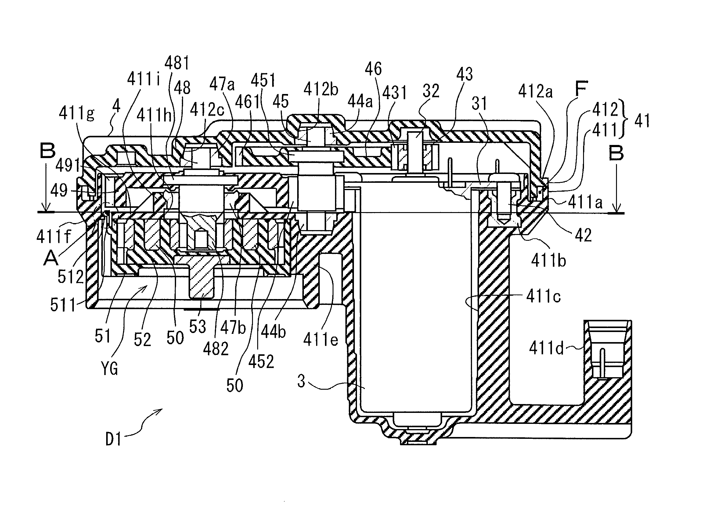
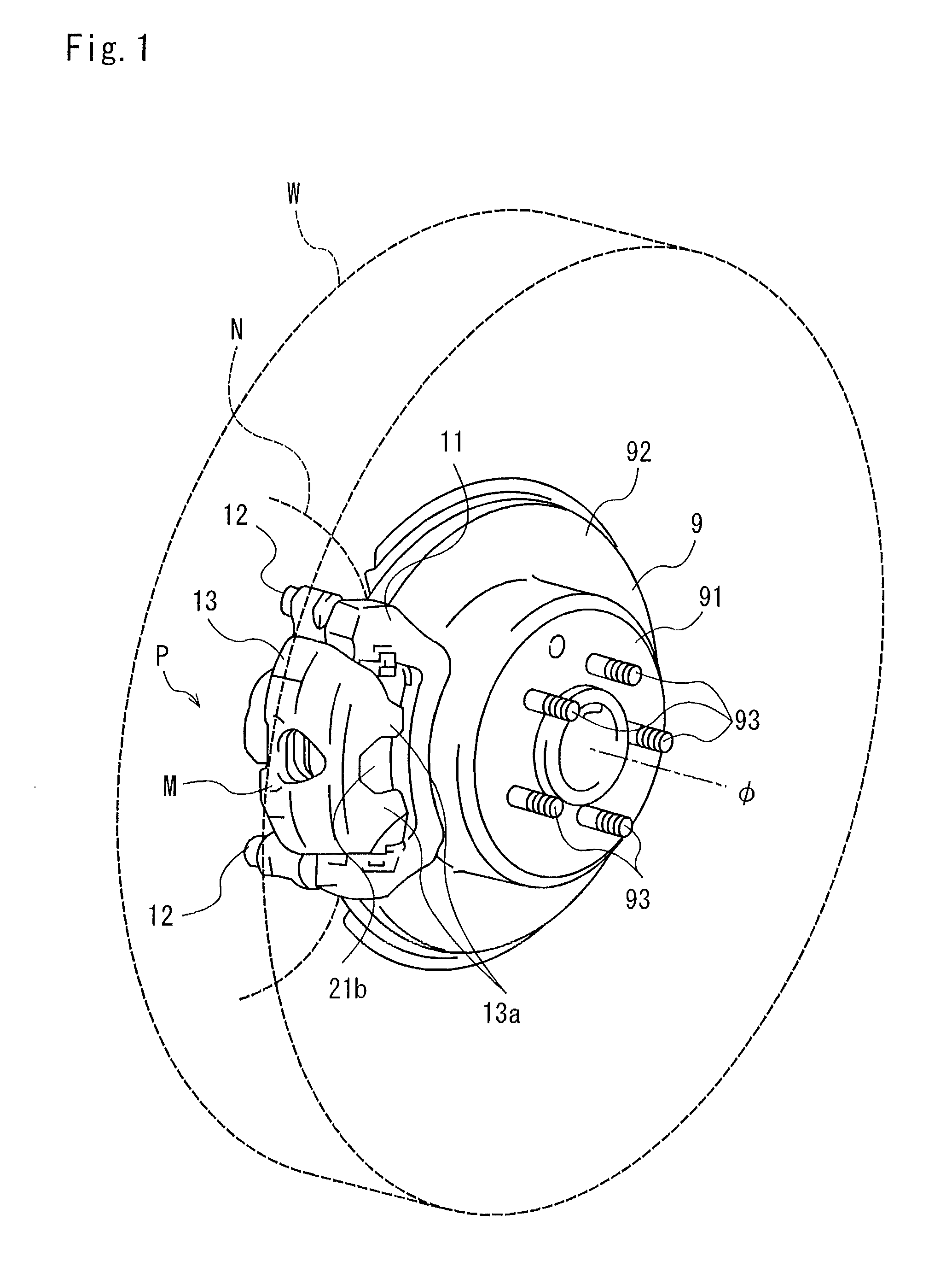
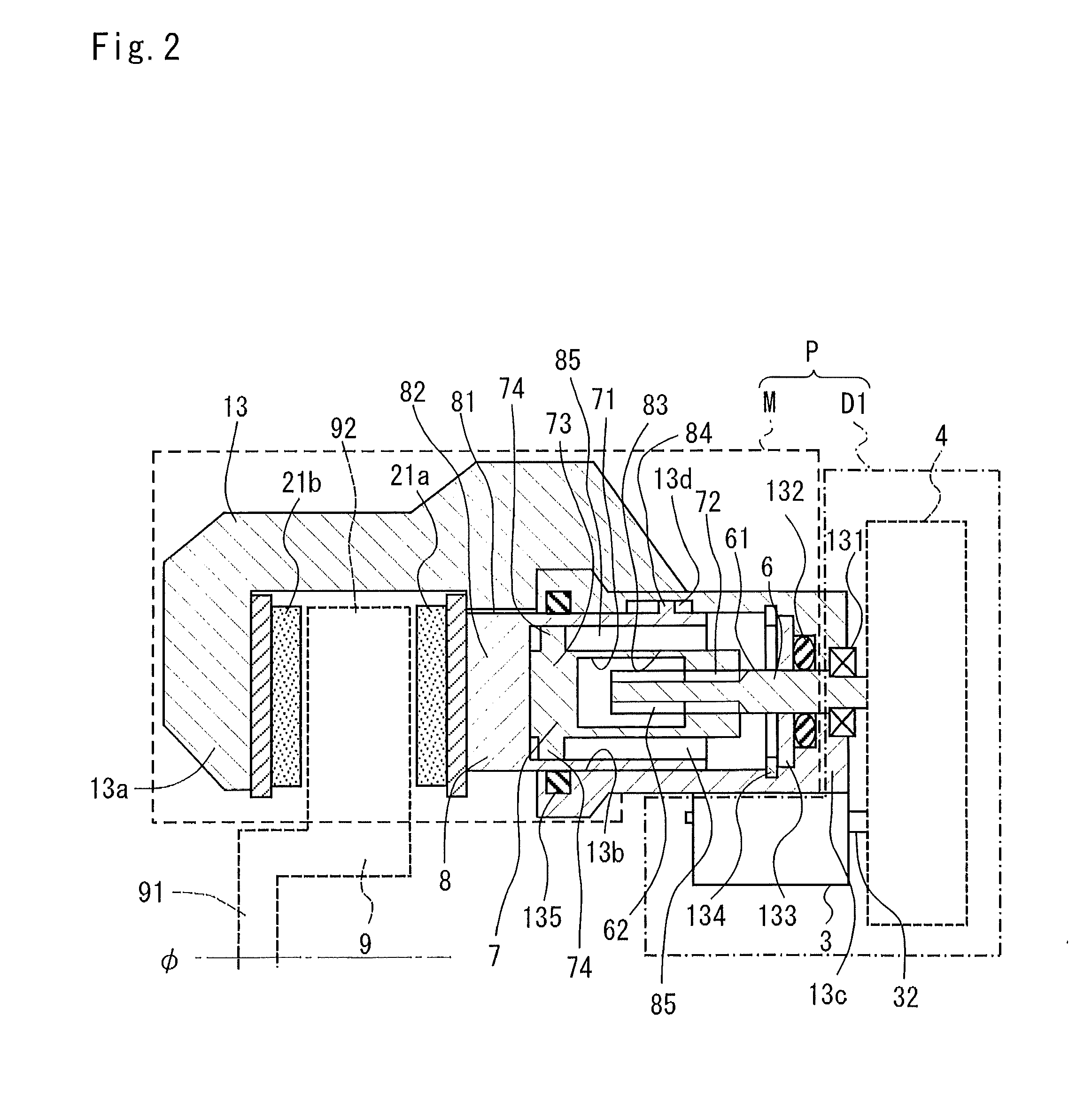
[0032]The electric parking brake device P according to the first embodiment will be explained with reference to FIGS. 1 through 5 of the attached drawings. The electric parking brake device P according to this embodiment is commonly used as a foot brake device which applies a braking force to a vehicle wheel W by a brake operating member operated by the driver of the vehicle during the vehicle running. It is noted here that the up-down direction in FIG. 3 corresponds to a direction of rotation axis φ of the disc rotor 9. Further it is noted that FIG. 2 is a schematically illustrated view of the electric parking brake device P and is not an accurately illustrated cross section view of an actual device.

[0033]The disc rotor 9 (corresponding to a disc of the invention), which is not a structural element of the invention, includes a but portion 91 projecting outside of the vehicle from the rotation center φ and a plate portion 92 formed around the periphery of the but ...

second embodiment

[0064]The driving device D2 according to the second embodiment will be explained based on FIG. 6 by explaining the differences in structure from the drive device D1 according to the first embodiment. It is noted here that the upward in FIG. 6 is used as an upward of the drive device D2 and the downward is used as a downward of the drive device D2. As shown in FIG. 6, a pivot pin 54 (corresponding to a first bearing portion of the invention) is used instead of the first gear shaft 45 as used in the drive device D1 of the first embodiment. The pivot pin 54 is fixed to the gear body 41 by press-fitting or by welding.

[0065]A gear member 56 is rotatably supported on the pivot pin 54 through a pair of bushes 55a and 55b. A first flange portion 561 is formed at the upward of the gear member 56 as similar to the first gear shaft 45 of the first embodiment and extending in a radial direction. Further as similar to the first embodiment, the first wheel gear 46 is fixed to the first flange por...


PUM


Abstract

A parking brake actuator generates and applies a braking force to a vehicle wheel by converting a rotation movement of a screw member which is rotated by an electric parking brake driving device into a translatory movement and transmitting the converted translatory movement to a piston to push a brake pad to a disc by the piston. The electric parking brake driving device includes an electric motor and a reduction gear mechanism which transmits the driving force of the electric motor to the electric parking brake driving device. The reduction gear mechanism includes a pinion gear fixed to an output shaft of the electric motor, a first gear shaft rotatably supported on a first bearing member provided on a gear body and a first wheel gear formed on the first gear shaft and engaging the first wheel gear to thereby reduce the speed of driving force of the electric motor.

Description

TECHNICAL FIELD[0001]This invention relates to an electric parking brake driving device and an electric parking brake device for applying braking force to a vehicle wheel by driving an electric motor upon vehicle parking.BACKGROUND OF THE TECHNOLOGY[0002]A conventional electric brake device has been known, which is installed in a vehicle wheel and applies braking force to the vehicle wheel by operating an electric motor (for example, see patent document 1). The electric brake device disclosed in the patent document 1 is formed by a small diameter pulley fixed to an output shaft of an electric motor and a large diameter pulley rotatably attached to a body and on which a belt is mounted over onto the small diameter pulley. The large diameter pulley is connected to a two-stage planetary gear set on the common rotation axis and a gear mechanism is formed thereon together with the large diameter pulley.[0003]According to thus structured electric brake device, the driving force of the ele...

Claims


Application Information

Patent Timeline
Patent Type & Authority Patents(United States)
IPC IPC(8): F16D65/00F16D55/225F16D65/18F16D55/08F16H25/20F16D55/00F16D125/50
CPCF16D65/18F16D55/225F16D2055/0004F16D2125/50F16H2025/2081F16H2025/2087
Inventor TAKEWAKI, MORIMASATAKEO, YUICHISAKAI, KOSUKEOZAWA, MASAKAZUTAKASU, KATSUHIKO
Owner ADVICS CO LTD
Why Eureka
Try Eureka