
Hearing assistance system

a technology of hearing aids and auxiliary devices, applied in the field of hearing aids, can solve the problems of poor sound quality, poor quality, cost and unsightly appearance, etc., and achieve the effect of blocking out environmental nois

Active Publication Date: 2016-03-29
HEARGLASS INC
View PDF32 Cites 7 Cited by
  • Summary
  • Abstract
  • Description
  • Claims
  • Application Information

AI Technical Summary

Benefits of technology

The present invention is about a unique wearable device that helps with hearing. This device can be attached to eyeglasses or appear like eyeglasses with an earphone or ear bud. It uses ultrasound to measure distances to objects around the user, and then creates tones based on that information. This allows the user to hear the audio representation of the surrounding objects while moving or scanning their head. The result is an advanced sound quality and a discreet appearance.

Problems solved by technology

Although hearing assistive instruments exist, they are often costly and unsightly, while the sound quality is mediocre at best.
The conventional hearing aids typically have a conspicuous appearance and provide poor sound quality.
The currently available hearing aids tend to be expensive and fail to achieve a design that is capable of striking a balance between providing a discrete appearance and high technology.

Method used


Image

  • Hearing assistance system
  • Hearing assistance system
  • Hearing assistance system

Examples


example earphones

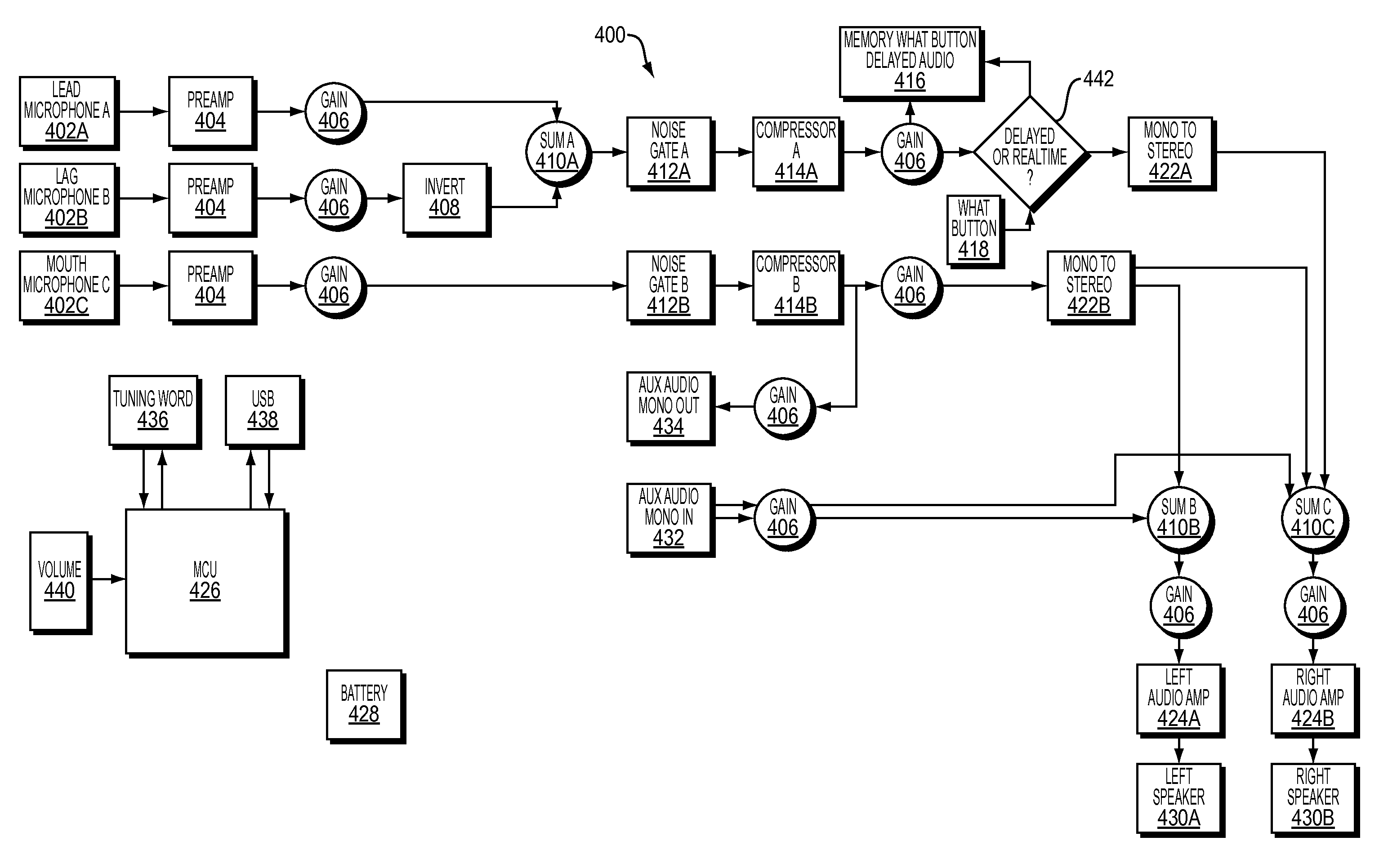
[0121]In one embodiment, for example as shown in FIG. 2B, speaker 224 may be situated on side 210. Speaker 224 may include a metallic package and may be coupled to a driver circuit in the electronic circuit block. Thus, sound signals (such as speech) received at microphones 218, 220, 222 may be processed and transmitted by electronic circuit block 228 to the drive circuit to drive speaker 224. In one embodiment, speaker 224 may include a tongue on which a first end of extension tube 226 may fit on.

[0122]In one embodiment, for example as shown in FIG. 2B, extension tube 226 may be flexible and composed of rubber or plastic. Extension tube 226 may include a hollowed core. A first end of extension tube 226 may be sealed by a first membrane, and a second end of extension tube 226 may be sealed by a second membrane. The first and second membranes may be passive radiator membrane that does not contain a voice coil or magnet assembly. The first end of extension tube 226 may include a ring ...

example v -

Example V-Channel Interlocks / Connecters for Earbud Attachment

[0128]The V-channel interlocks / connectors for earbud attachment is a similar embodiment to the cone shaped interlocks / connectors for earphone attachment. The V-channel connectors embodiment, the speaker is connected to the same flexible hollow tube 226 as described for the cone shaped connector. As shown in FIG. 2M-1 through 2M-3, in the V-channel embodiment, an earbud 207 may be attached to an arching shaped earclip 205, such as shown in 213, which may be positioned over the user's ear. The hollow tube 226 may be positioned inside the earclip 205 and attaches to the earbud 207 when the earbud 207 is secured at the bottom of the earclip. At the top of the earclip 205, a connector 203 may be position on the earclip 205 by means of a ball joint, and attached to the connector may be a male “V” shaped channel 211. An interlock strip 201 with female “V” shaped hole 209 may be mounted on the glasses at201 where the ear meets the...

example side frame batteries

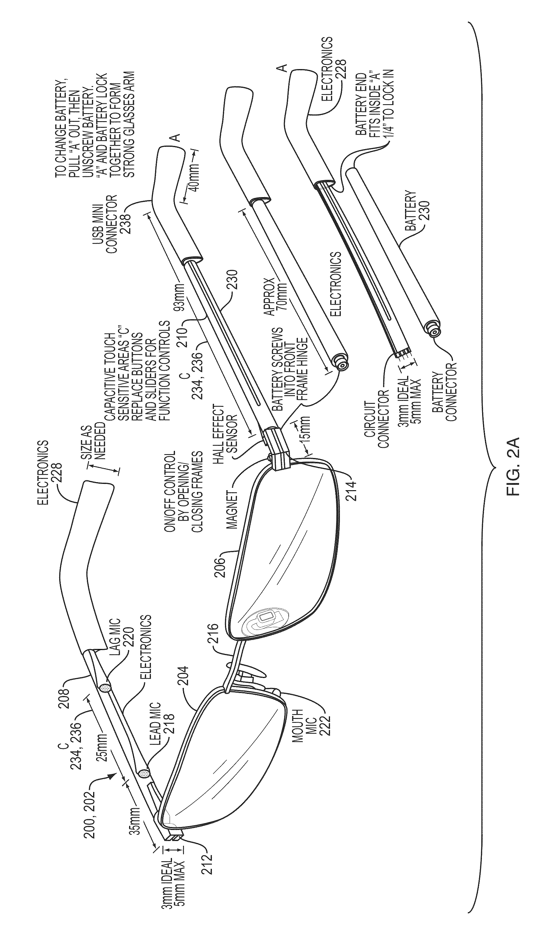
[0133]FIGS. 2E and 2F illustrate a hearing assistance device 200 according to other embodiments of the disclosure. In some embodiments, the hearing assistance device 200 may be built around a pair of glasses 202 including rims 204, 206, sides 208, 210, hinges 212, 214 for connecting sides 208, 210 to rims 204, 206, and a bridge 216 for connecting rims 204, 206. Rims 204, 206 may hold lenses so that the glasses 202 may function as a visual correction apparatus.

[0134]In example embodiments with details shown in FIGS. 2E and 2F, the hearing assistance device 200 may include a lead microphone 218, a lag microphone 220, a mouth microphone 222, and an electronic circuit block 228. In some embodiments, the hearing assistance device may include capacitive touch sensitive areas 234 and 236. The hearing assistance device 200 may further optionally include an ear bud or earphone. A battery may be magnetically attached to the frame, and the battery may form part of side 210. In some embodiments...


PUM


Abstract

The present universal wearable computing device relates to a hearing assistance system, device, method, and apparatus that provide a discreet approach to user hearing assistance, without relying on a conventional hearing aid. The hearing assistance system and the requisite electronics may be incorporated into frames that also function as eyeglasses with earphone(s) that may be connected to the frame to assist user hearing. An earphone may be configured with minimal electronics, such that a power source enable sound transmissions to the ear, is provided by a connection to the frame of the eyeglasses. In another example, the earphone is configured without any electronics and sound is transmitted to the user / listener's ear(s) via a psychoacoustic system. The sound quality of the transmissions to the earphones may be optimized using a tuning / equalizer application operating from a computing device, such as an app on a mobile device. The tuning / equalizer application can be used by the user / listener to optimize volume input levels to the earphone(s).

Description

RELATED APPLICATIONS[0001]This application claims the benefit of U.S. Provisional Application No. 62 / 023,797, filed on Jul. 11, 2014 and U.S. Provisional Application No. 61 / 928,958, filed on Jan. 17, 2014. The entire teachings of the above applications are incorporated herein by reference.BACKGROUND[0002]Standard hearing aids include behind-the-ear (BTE), mini-BTE, and receiver-in-the-canal (RIC) devices. Such hearing assistance devices typically include sophisticated electronics to ensure the sound quality. Often, the designs of in-ear or behind-the-ear hearing assistance devices are limited by the space available at human ears.[0003]Hearing aids, for example, may include sophisticated electronics for suppressing environmental noise and amplifying the speech signal. Moreover, hearing aids may have different styles such as in-canal and inside the outer ear. The limited physical spaces inside the canals or the outer ear of human subject limit the size of circuits that may be deployed...

Claims


Application Information

Patent Timeline
Patent Type & Authority Patents(United States)
IPC IPC(8): H04R25/00H04R1/10G02C11/06G10L13/04G02C5/00G10L21/0208
CPCH04R25/405G02C5/006G02C11/06G10L13/043G10L21/0208H04R1/1066H04R25/407H04R25/558H04R25/604H04R25/65H04R2225/41H04R2225/43H04R2225/61H04R2225/63H04R2430/21H04R2460/01H04R25/603H04R2225/0213G10L13/00H04R1/028H04R1/2853H04R25/402H04R25/48H04R2420/09
Inventor SPRAGUE, PETER, J.BOYLE, WAYNE, D.
Owner HEARGLASS INC
Learn More