Hollow profile for a weight-in-motion sensor

a technology of motion sensor and hollow profile, which is applied in the direction of weighing apparatus, measuring devices, instruments, etc., can solve the problems of plastic deformation, inability to accurately control the transmission from the outside to the tube, and less suitable systems, so as to reduce the sensitivity of the completed wim sensor

Active Publication Date: 2016-04-05
KISTLER HLDG AG
View PDF33 Cites 18 Cited by
  • Summary
  • Abstract
  • Description
  • Claims
  • Application Information

AI Technical Summary

Benefits of technology

[0012]It is the object of the present invention to state a hollow profile of the type mentioned in the introduction, which hollow profile withstands the loads experienced in use for a longer period of time without this diminishing the sensitivity of the completed WIM sensor. The object is met by the characteristics described below.
[0014]It has been shown that these relatively thin regions on the tube segments act in the manner of flexure hinges that permit bending in these regions more easily than do, in particular, relatively thick regions which have been stiffened by means of reinforcement of the wall thickness. Since, during bending, less stress is generated in relatively thin positions than in relatively thick positions, the service life of profiles according to the invention is longer when compared to conventional hollow profiles.

Problems solved by technology

Such systems have shown to be less suitable because the force transmission from the outside to the tube can be controlled only inaccurately.
In the case of an insufficient wall thickness 9, these load peaks result in plastic deformation.
This would result in a change in the measuring characteristics of the sensor, in the formation of cracks, and in failure of the sensor.
Preloading the measuring element generates significant stress in the tubular part.
Additional high stress in the tubular part is generated when heavy vehicles drive over the sensor in the installed state.
Since this represents a dynamic load, and frequently high load cycles are experienced when vehicles drive over the device, the profile is subjected to permanent damage, in particular in the region of the transition from the tubular part to the force-transmission plates.
It has been shown that conventional tubular profiles cannot withstand the operating loads of WIM applications.
Since the tubular part forms a force shunt that reduces the sensitivity of the sensor and thus impairs the measuring results, said tubular part should be designed so as to be as thin-walled as possible and it should not be unnecessarily reinforced.

Method used


Image

  • Hollow profile for a weight-in-motion sensor
  • Hollow profile for a weight-in-motion sensor
  • Hollow profile for a weight-in-motion sensor

Examples


Embodiment Construction

[0023]Below, the invention is described in more detail with reference to the figures. The same circumstances have identical reference characters.

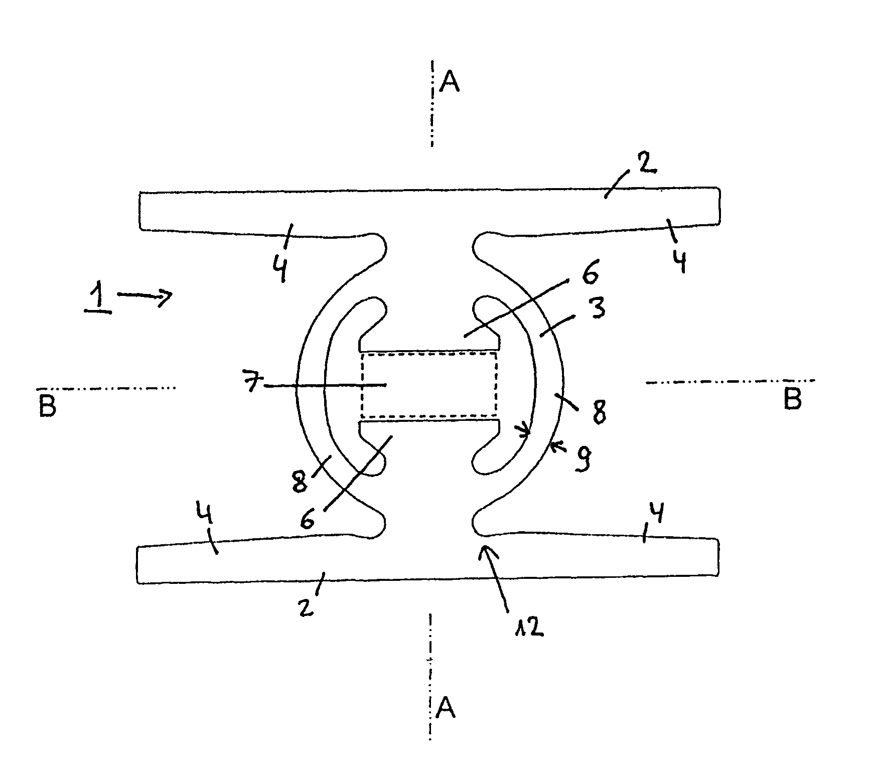
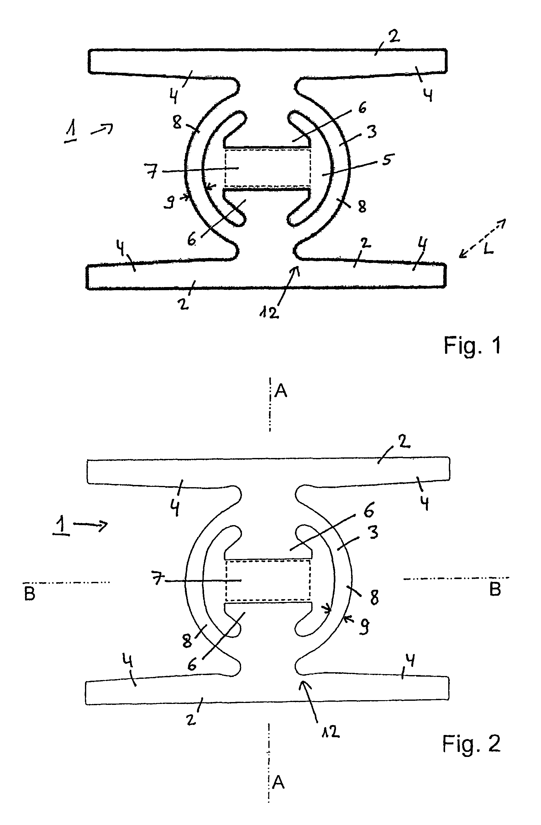
[0024]FIG. 2 shows a cross section of a hollow profile 1 according to the invention, which hollow profile 1, apart from a few differences, is designed like the hollow profile according to the state of the art, which hollow profile has been described above. The components are essentially identical and are thus not listed anew.

[0025]In particular, in the embodiment according to the invention the parallel force-transmission plates 2 are wider, by a factor of 1.5 to 3 times, than the tube 3 arranged between the aforesaid. As a result of this a defined force transmission of a vehicle passing over the device is defined. Since the tube 3 is designed so as to be essentially round, the connection between the tube 3 and the force-transmission plates 2 is minimal when compared to the width of the force-transmission plates 2. This installation results ...


PUM

PropertyMeasurementUnit
lengthaaaaaaaaaa
lengthaaaaaaaaaa
thicknessaaaaaaaaaa

Abstract

A WIM (weigh-in-motion) sensor has an oblong hollow profile and includes two force-transmission plates arranged parallel to each other. A tube is arranged between the plates and is integrally formed with the plates and defines a hollow space. Two supports that are arranged opposite one another are formed inside the hollow space, each support extending away from a respective plate and between which a measuring element is received centrally in the tube under preload. The tube includes two tube segments designed to be mirror-symmetrical with respect to each other, which join the plates together and on the inside adjoin the hollow space. The wall thickness of each tube segment has a relatively thick region between at least two relatively thin regions.

Description

CROSS-REFERENCE TO RELATED APPLICATIONS[0001]This application claims priority to International Application Serial No. PCT / CH2012 / 000251, filed Nov. 15, 2012, which claims priority to Swiss Application No. 1846 / 11 filed Nov. 18, 2011. International Application Serial No. PCT / CH2012 / 000251 is hereby incorporated herein for all purposes by this reference.FIELD OF THE INVENTION[0002]The invention relates to an oblong hollow profile for a WIM (weigh in motion) sensor, comprising two force-transmission plates arranged parallel to each other and a tube arranged between said plates and integrally formed with the plates and forming a hollow space, wherein two supports that are arranged opposite one another are formed inside the hollow space, each one extending away from a respective plate, between which supports a measuring element can be received centrally in the tube under preload, and wherein the tube comprises two tube segments designed to be mirror-symmetrical with respect to each other...

Claims


Application Information

Patent Timeline
Patent Type & Authority Patents(United States)
IPC IPC(8): G01L1/04G01G21/14G01G3/13G01G19/02
CPCG01G21/14G01G3/13G01G19/024G01L1/04
Inventor CORNU, DAVIDHOFMANN, ADRIAN
Owner KISTLER HLDG AG
Why Eureka
Try Eureka