Electromagnetic DC pulse power system including integrated fault limiter

a technology of pulse power system and fault limiter, which is applied in the direction of power conversion system, emergency protective arrangement for limiting excess voltage/current, electrical equipment, etc., can solve the problem of damage beyond repair of the pulse power system, and achieve the effect of enhancing overall safety and high voltage isolation

Active Publication Date: 2016-04-05
RAYTHEON CO
View PDF22 Cites 10 Cited by
  • Summary
  • Abstract
  • Description
  • Claims
  • Application Information

AI Technical Summary

Benefits of technology

[0004]According to an exemplary embodiment, an electromagnetic direct current (DC) power system includes a plurality of pulse forming networks (PFN) modules. Each pulse forming network (PFN) module includes a PFN circuit, a fault current limiting (FCL) circuit and a cooling system. The pulse PFN circuit is configured to generate a pulsed DC output power. The PFN circuit further includes at least one storage inductor with at least one primary winding having a primary inductance that controls a primary impedance of the PFN circuit. Typically the energy storage inductor is connected in series with the energy storage capacitor and an electronic commutating device or electromechanical circuit interruption element. The FCL circuit includes a secondary winding that is magnetically coupled with the primary winding. The FCL circuit is configured to receive fault energy existing in the PFN circuit during a fault event. The cooling system is configured to cool at least one of the primary winding and the secondary winding. The FCL secondary winding provides high voltage isolation from the primary winding to assist with fault reduction and to enhance overall safety.
[0006]According to another exemplary embodiment, a method of protecting an electromagnetic DC power system from fault energy delivered to a pulse forming network (PFN) circuit during a fault event comprises electromagnetically coupling a fault current limiting (FCL) circuit to the PFN circuit. The method further includes detecting the fault event in the PFN circuit, and adjusting the secondary impedance of the FCL circuit to control a primary impedance of the PFN circuit. The method further includes transferring the fault energy from the PFN circuit to the FCL circuit in response to controlling the impedance of the PFN circuit, and protecting sensitive circuit components such as the main switching devices from excessive current levels.

Problems solved by technology

If a system fault occurs, such as a short circuit, peak current levels, for example 10 MA, may be inadvertently delivered to components of the PFN such that the pulse power system is damaged beyond repair.

Method used


Image

  • Electromagnetic DC pulse power system including integrated fault limiter
  • Electromagnetic DC pulse power system including integrated fault limiter
  • Electromagnetic DC pulse power system including integrated fault limiter

Examples


Embodiment Construction

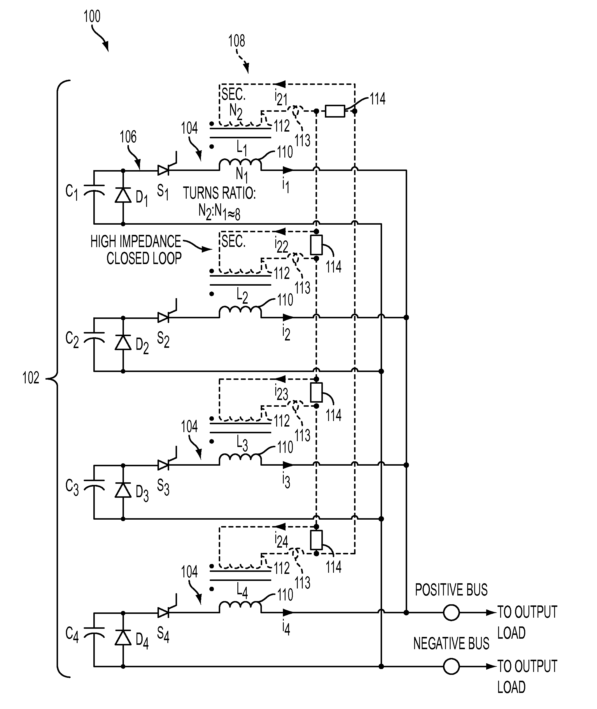
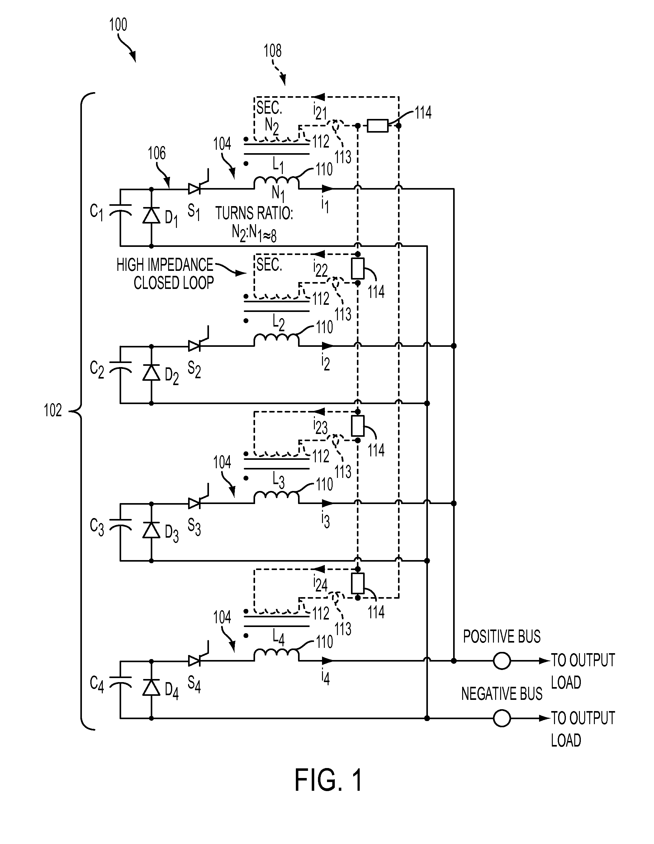
[0019]Referring to FIG. 1, an exemplary embodiment of an electromagnetic direct current (DC) pulse power system 100 is illustrated. The electromagnetic DC pulse power system 100 includes one or more PFN stacks 102. Each PFN stack 102 includes one or more PFN modules 104. Although a single PFN stack 102 is illustrated, the PFN stack 102 may be part of a larger system of identical PFN modules configured to produce a high-current, fast-pulse output to a common load. Although the PFN stack 102 illustrated in FIG. 1 includes four PFN modules 104, the number of PFN modules 104 is not limited thereto. For example, the PFN stack 102 may include less than two PFN modules 104 or more than four PFN modules 104.

[0020]The PFN stack 102 may generate energy ranging from approximately 1 kilojoule per stack (1 kJ / stack) to approximately 10,000 kJ / stack. In addition, the exemplary embodiment of FIG. 1 illustrates the PFN modules 104 arranged in a common PFN stack 102. The PFN modules 104 may be conne...


PUM


Abstract

An electromagnetic direct current (DC) power system includes a plurality of pulse forming networks (PFN) modules. Each pulse forming network (PFN) module includes a PFN circuit, a fault current limiting (FCL) circuit and a cooling system. The pulse PFN circuit is configured to generate a pulsed DC output power. The PFN circuit further includes at least one energy storage inductor with primary winding having a primary winding inductance that controls a primary impedance of the PFN circuit. The FCL circuit includes a secondary winding that electrically communicates with the primary winding. The FCL circuit is configured to receive fault energy existing in the PFN circuit during a fault event. The cooling system is configured to cool at least one of the primary winding and the secondary winding, and remove a portion of the fault energy.

Description

GOVERNMENT CONTRACT[0001]This invention was made with Government support under N000024-12-C-4223 Technical Instruction #1 awarded by the United States Navy. The Government has certain rights in the invention.BACKGROUND[0002]The present disclosure relates to electromagnetic pulse power systems, and more particularly, to high power electromagnetic direct current (DC) pulse power systems including a pulse forming network (PFN).[0003]Electromagnetic DC pulse power systems utilize one or more PFNs to shape and control discrete quantities of energy which are characterized by fast rise-times in either voltage, current or power. Conventional PFNs typically arrange a combination of inductors and capacitors in a transmission line, i.e., circuit network, to yield specific source impedances, specific rise times, and specific fall times. These PFNs typically output high energy levels. For example, conventional PFNs may output voltage levels exceeding 100 kilovolts (kV), current levels exceeding ...

Claims


Application Information

Patent Timeline
Patent Type & Authority Patents(United States)
IPC IPC(8): H02H9/02H02M1/32H03K3/37
CPCH02H9/02H02M1/32
Inventor KUZNETSOV, STEPHEN B.
Owner RAYTHEON CO
Why Eureka
Try Eureka