Controlling turn on FETs of a hot plug device

a technology of hot plugs and turn-on fets, which is applied in the direction of electronic switching, pulse techniques, instruments, etc., can solve the problems of severe burn in the server environment, severe power dissipation of the turn-on fets,

Inactive Publication Date: 2016-04-05
INT BUSINESS MASCH CORP
View PDF13 Cites 3 Cited by
  • Summary
  • Abstract
  • Description
  • Claims
  • Application Information

AI Technical Summary

Benefits of technology

The patent text describes a method for preventing damage to FETs and ensuring safe operation in a device by controlling the number and duration of turn on pulses. The method limits the series of turn on pulses to no more than a predetermined number to prevent damage to the FETs and tripping of the power supply. The duration of each pulse is set to allow the impedance of the FETs to remain high and pre-charging of the gate can occur. The turn off time is chosen to prevent the rise in rail voltage above a predetermined threshold. The method also reduces power dissipation in the FETs compared to providing a steady turn on signal.

Problems solved by technology

The main issue seen in industry is the fact there is an impedance that is lower than the over current trip point, but high enough to damage a FET if turned on into this impedance.
This exposes hot plug mechanisms to cases where, if there is a failure on the rail and the impedance is a soft short, it can lead to severe power dissipation in the turn on FETs, and can lead to a double fault causing a severe burn in a server environment.

Method used


Image

  • Controlling turn on FETs of a hot plug device
  • Controlling turn on FETs of a hot plug device
  • Controlling turn on FETs of a hot plug device

Examples


Embodiment Construction

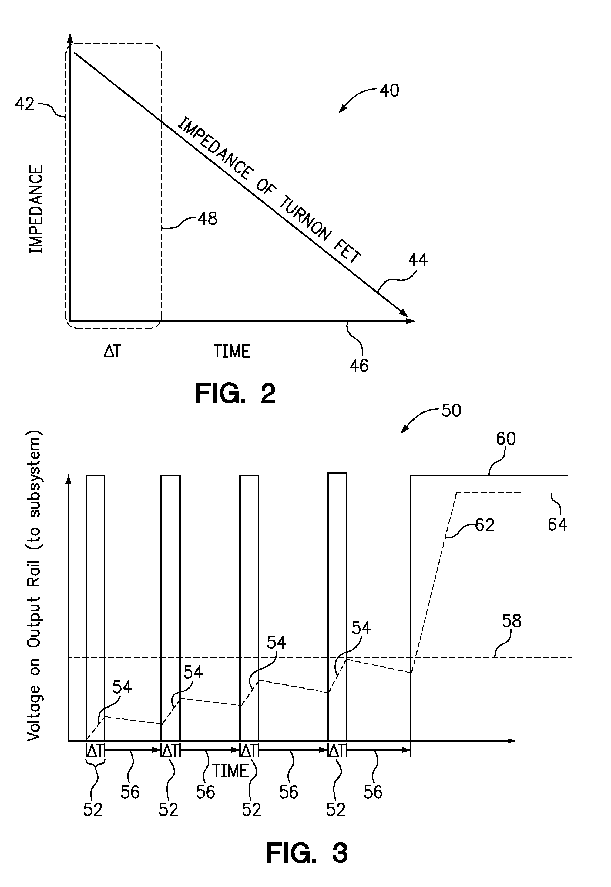
[0010]One embodiment of the present invention provides a method, comprising providing a series of turn on pulses to the gates of a plurality of turn on FETs on a hot plug device coupled to a direct current power source, wherein each pulse causes the plurality of FETs to pass current from the direct current power source to a subsystem of the hot plug device, and wherein each pulse has a duration that ends before the impedance of the turn on FETs falls below a safe operating region. The method further comprises providing a steady turn on signal to the FETs in response to the output voltage from the FETs to a subsystem of the hot plug device exceeding a predetermined voltage threshold.

[0011]A hot plug device is an electronic device that can be added to a host system without significant interruption in the operation of the system. A typical hot plug device will have a connector with pins that include an electrical ground, power and any number of signal lines. Accordingly, the physical c...


PUM


Abstract

A computer program product for controlling the in rush current to a hot plug device. The computer program product includes program instructions that cause a processor to perform a method. The method includes providing a series of turn on pulses to the gates of a plurality of turn on FETs on a hot plug device coupled to a direct current power source, wherein each pulse causes the plurality of FETs to pass current from the direct current power source to a subsystem of the hot plug device, and wherein each pulse has a duration that ends before the impedance of the turn on FETs falls below a safe operating region. The method further includes providing a steady turn on signal to the FETs in response to the output voltage from the FETs to a subsystem of the hot plug device exceeding a predetermined voltage threshold.

Description

BACKGROUND[0001]1. Field of the Invention[0002]The present invention relates to hot plug devices and methods of controlling power to a hot plug device.[0003]2. Background of the Related Art[0004]Many systems require the ability to hot plug a device into the system, and control the inrush current seen by the charging of input capacitance. In most technologies there is a balance between charging the capacitance as fast as you can so the FETs are not in a linear mode too long, and not tripping the over current of the regulator or any other upstream power supply. The main issue seen in industry is the fact there is an impedance that is lower than the over current trip point, but high enough to damage a FET if turned on into this impedance. This exposes hot plug mechanisms to cases where, if there is a failure on the rail and the impedance is a soft short, it can lead to severe power dissipation in the turn on FETs, and can lead to a double fault causing a severe burn in a server environ...

Claims


Application Information

Patent Timeline
Patent Type & Authority Patents(United States)
IPC IPC(8): H02H7/20H03K17/693G06F13/40G05F1/569
CPCH03K17/693G06F13/4081H02H7/205G05F1/569G06F13/40H02H7/20H02H9/004H03K17/08H03K17/687H02H9/001H02H9/025H02H11/005
Inventor BARNETTE, JAMAICA L.CELENZA, NICHOLASTOTTEN, BRIAN C.
Owner INT BUSINESS MASCH CORP
Why Eureka
Try Eureka