Droplet dispensing device and light source comprising such a droplet dispensing device

a technology of droplet dispensing device and light source, which is applied in the direction of spraying apparatus, electrical discharge tubes, electrical apparatus, etc., can solve the problems of insufficient precision and improve efficiency, so as to improve the accuracy of droplet size and trajectory

Active Publication Date: 2016-04-05
ETH ZZURICH
View PDF22 Cites 6 Cited by
  • Summary
  • Abstract
  • Description
  • Claims
  • Application Information

AI Technical Summary

Benefits of technology

[0013]It is an object of the invention, to create a droplet dispensing device with improved precision of the droplet size and trajectory even when the liquid used is a molten material from a heated reservoir.
[0014]It is another object of the invention to have a light source with an improved efficiency.
[0031]According to another embodiment of the invention a heat shield is provided for at least part of said piston, which reduces the heat flux from the liquid material to said piezoelectric actuator.

Problems solved by technology

The formation and delivery of the target material to the focus of the light collector is closely linked to thermal and fluid management, as well as droplet generation issues of the dispensing device.
The droplet dispensing devices known so far have the disadvantage that the droplet size and trajectory are not precise enough to generate extreme ultra-violet or soft x-ray radiation in a laser-driven light source with improved efficiency.

Method used


Image

  • Droplet dispensing device and light source comprising such a droplet dispensing device
  • Droplet dispensing device and light source comprising such a droplet dispensing device
  • Droplet dispensing device and light source comprising such a droplet dispensing device

Examples


Embodiment Construction

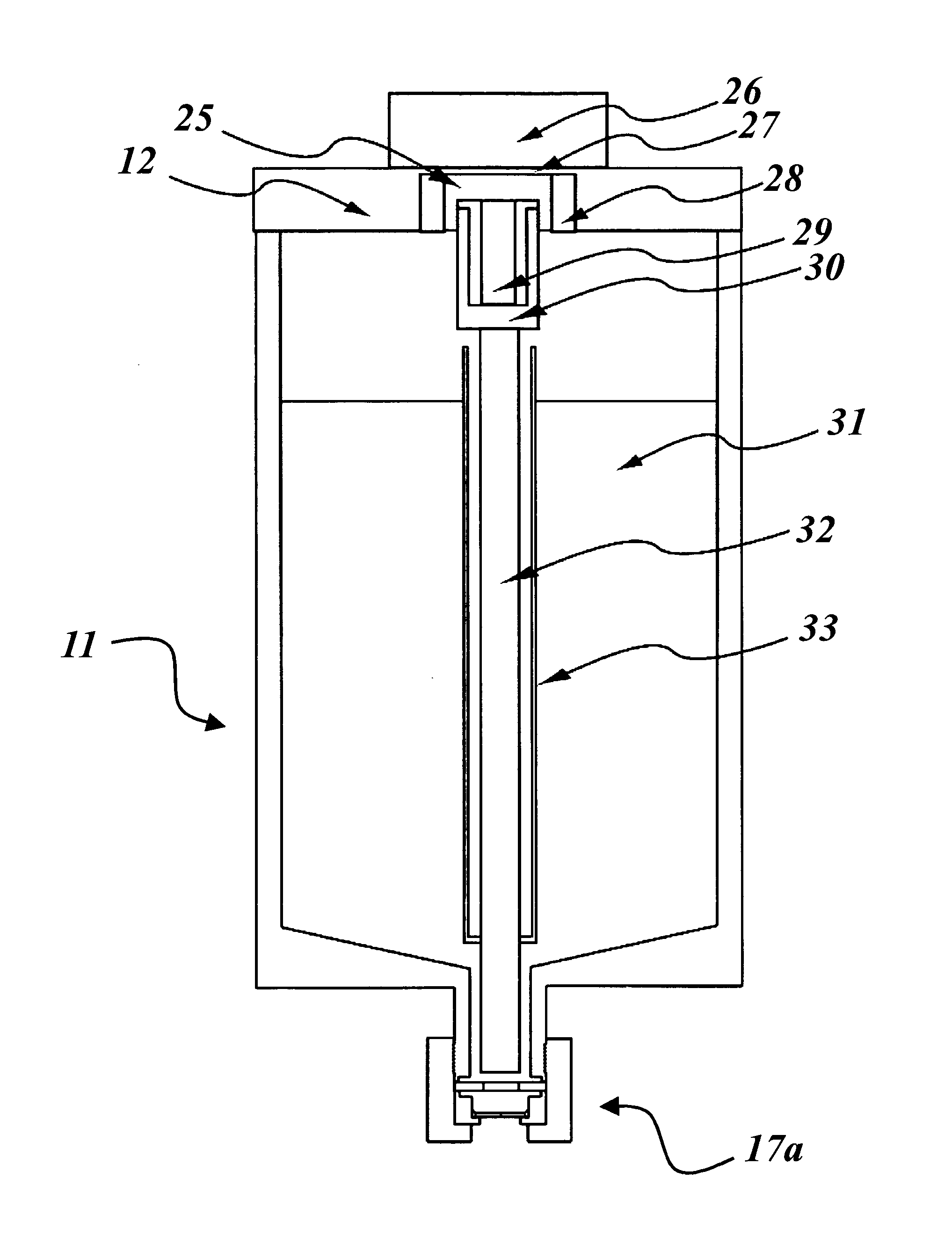
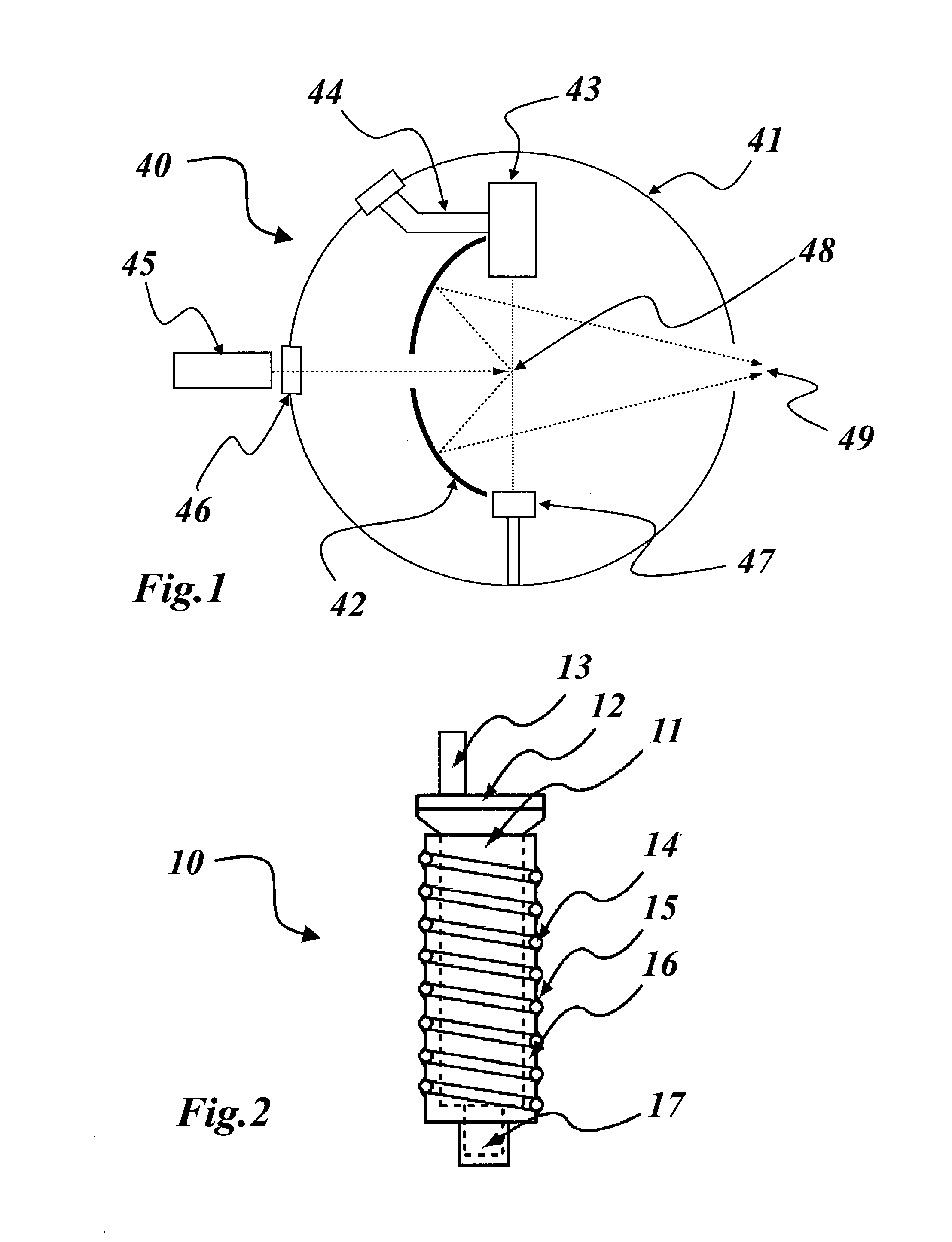
[0042]The invention is directed to a droplet dispensing device which can be used for various purposes. The invention also encompasses a light source, comprising a production chamber that contains a light production site, a droplet dispensing device for dispensing droplets of a material into the production site, the material being capable of radiating in the target wavelength window when excited into a higher energy state, and irradiating means for irradiating the droplets in the production site. Said droplet dispensing device is a droplet dispensing device according to the invention.

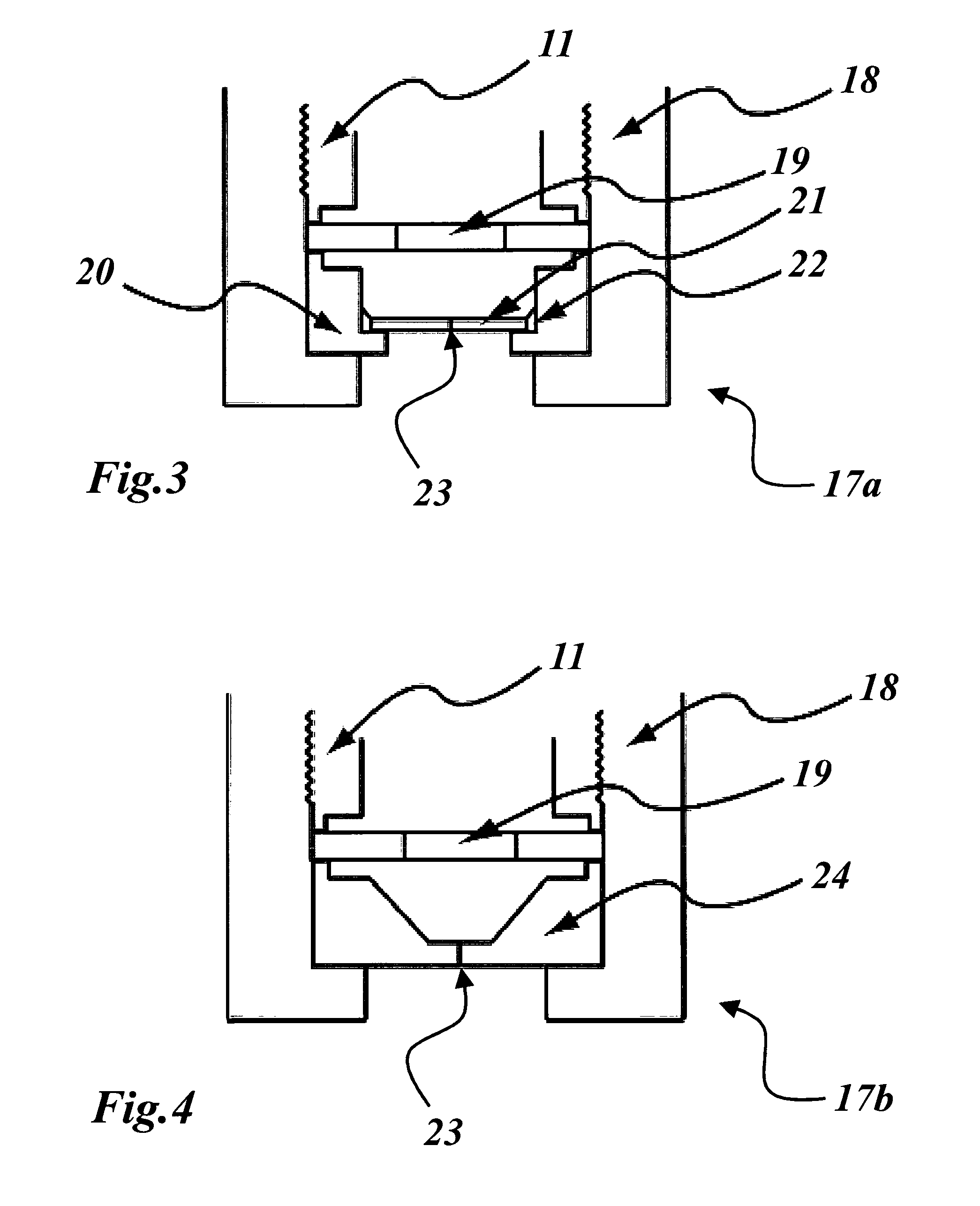
[0043]In one embodiment the material reservoir and nozzle may be heated using an electrical heating resistance. Droplet generation is achieved by an actuated piston inside the material reservoir. The excitation source of said piston is a piezoelectric actuator. The piston may be provided with a cooling system and a heat shield for said actuator. The material reservoir may be a replaceable and refillable ...


PUM


Abstract

A droplet dispensing device includes a reservoir for receiving a liquid material, an outlet nozzle in fluid communication with the reservoir and a piezoelectric actuating means acting on the liquid material at the outlet nozzle to exit the outlet nozzle in a sequence of droplets. A piezoelectric actuating means that includes a piston, which is actuated by a piezoelectric actuator at one end and dips the other, free end into the liquid material is provided just upstream of the outlet nozzle.

Description

CROSS-REFERENCE TO RELATED APPLICATIONS[0001]This application is the United States national phase of International Application No. PCT / EP2012 / 001453 filed Apr. 2, 2012, and claims priority to European Patent Application No. 11002817.2 filed on Apr. 5, 2011, the disclosures of which are hereby incorporated by reference in their entirety.BACKGROUND OF THE INVENTION[0002]1. Field of the Invention[0003]The present invention relates to the technical field of generating droplets and, more particularly to a droplet dispensing device. It further refers to a light source comprising such a droplet dispensing device.[0004]2. Description of Related Art[0005]In different technical fields it is necessary to generate a continuous sequence of droplets of a predetermined size and droplet frequency, which is ejected on a predetermined trajectory. The material of the droplets may for example be a liquid solution or a molten metal. One technical field, where such a droplet dispensing device is used, is...

Claims


Application Information

Patent Timeline
Patent Type & Authority Patents(United States)
IPC IPC(8): H05G2/00B05B1/02B05B17/06
CPCH05G2/008B05B1/02B05B17/0623H05G2/005H05G2/006
Inventor ROLLINGER, BOBABHARI, REZAGIOVANNINI, ANDREAHENDERSON, IAN
Owner ETH ZZURICH
Why Eureka
Try Eureka