Load and source pull test system for RF and baseband frequencies

a test system and source pull technology, applied in the direction of resistance/reactance/impedence, instruments, measurement devices, etc., can solve the problem of limited use of standard equipment in the prior ar

Active Publication Date: 2016-04-12
TSIRONIS CHRISTOS
View PDF6 Cites 7 Cited by
  • Summary
  • Abstract
  • Description
  • Claims
  • Application Information

AI Technical Summary

Problems solved by technology

In this context prior art is limited to the use of standard equipment, like signal sources, power meters, spectrum analyzers etc. and RF

Method used


Image

  • Load and source pull test system for RF and baseband frequencies
  • Load and source pull test system for RF and baseband frequencies
  • Load and source pull test system for RF and baseband frequencies

Examples


Embodiment Construction

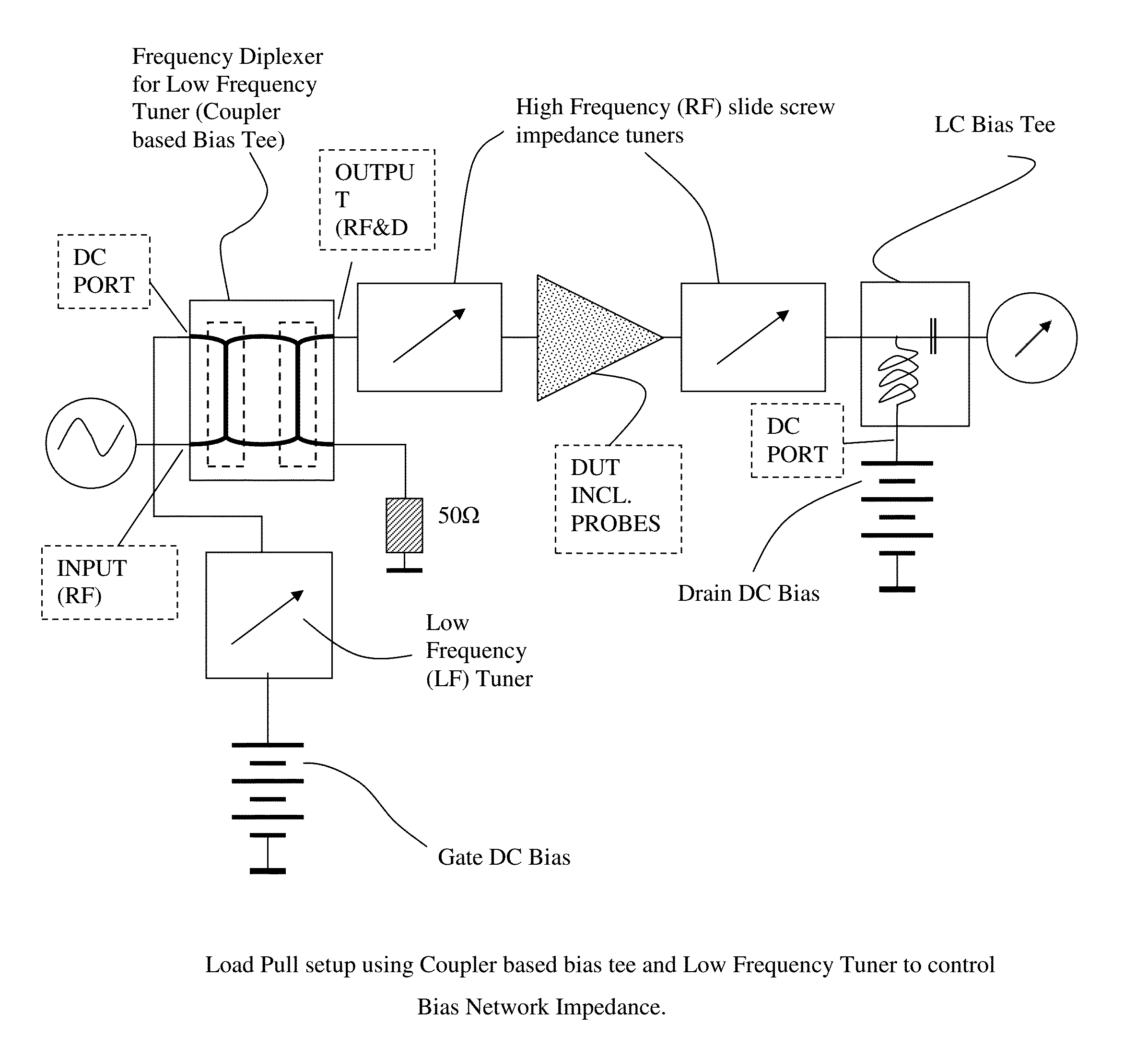
[0038]The setup proposed here uses DC Bias Tees as a frequency Diplexer (or frequency separator) FIGS. 5, 6, 8. The Bias Tee allows RF frequencies to pass through from the signal source to the DUT at very low insertion loss. A blocking chip capacitor of adequate size (1 to a few Picofarad, pF, FIGS. 4, 5) inserted in the signal path is an appropriate solution. The DC path is blocked for the RF signal by an inductor (FIG. 5). The power supply following the inductor has, in general, very low internal impedance, close to OQ. Sometimes a high value parallel capacitor is connected after the inductor to make certain the foot of the inductor is properly grounded (not shown in FIG. 5). The Bias Tee inductor and following power supply, including shunt capacitor and possible cables represent a non-negligible impedance at baseband frequencies up to around 20 MHz! Instead it does represent unknown and uncontrolled impedance, which has, in many cases, a deteriorating effect on the performance of...


PUM


Abstract

A load pull measurement setup allows independent impedance tuning at RF frequencies at the output of the DUT as well as independent tuning at RF and baseband frequencies of the modulated signal at the input of the DUT. This allows optimizing baseband frequency impedances for nonlinear amplifier performance when processing modulated signal, such as IMD, ACPR etc. Baseband tuning is done using a low frequency programmable impedance tuner, which is connected through the input bias tee, which acts as a frequency separator (diplexer). The input bias tee may be an LC based network or a 3 dB matched coupler based network.

Description

CROSS REFERENCE[0001]This application is a continuation of U.S. Non-Provisional patent application Ser. No. 13 / 371,587 filed Feb. 13, 2012 and titled CALIBRATION PROCEDURE FOR A LOAD AND SOURCE PULL TEST SYSTEM FOR RF AND BASEBAND FREQUENCIES, which itself is a continuation of application Ser. No. 12 / 219,793, filed Jul. 29, 2008 and titled LOAD AND SOURCE PULL SETUP FOR RF AND BASEBAND FREQUENCIES, both of which are incorporated herein by reference in their entireties.PRIORITY CLAIM[0002]Not applicable.CROSS-REFERENCE TO RELATED ARTICLES[0003][1] U.S. patent application Ser. No. 11 / 498,241, Load pull tuner using self-aligning single and double probes.[0004][2]“Three probe tuner tackles multiple tasks”, Microwaves & RF Magazine, February 2005, page 90ff.[0005][3] U.S. Pat. No. 7,646,267, “Low Frequency Electromechanical Impedance Tuner.”[0006][4]“High-Power Load Pull at 40 MHz Using Low Frequency iTuners (iLFT)”, Powerpoint presentation, at IMS 2007.[0007][5]“Adjacent Channel Power r...

Claims


Application Information

Patent Timeline
IPC IPC(8): G01R27/32G01R27/28
CPCG01R27/28
Inventor TSIRONIS, CHRISTOS
Owner TSIRONIS CHRISTOS
Why Eureka
Try Eureka