Split cage and roller bearing

a roller bearing and radially inner portion technology, applied in the direction of bearings, shafts and bearings, rotary bearings, etc., can solve the problems of likely occurrence of abnormal abrasion between the radially inner portion and the roller, and achieve the effect of preventing the occurrence of abnormal abrasion

Active Publication Date: 2016-04-19
JTEKT CORP
View PDF5 Cites 2 Cited by
  • Summary
  • Abstract
  • Description
  • Claims
  • Application Information

AI Technical Summary

Benefits of technology

[0007]One object of the invention is to provide a split cage and a roller bearing that are configured to prevent occurrence of abnormal abrasion of a pocket-side face of each cage segment even if a clearance between adjacent cage segments is eliminated.

Problems solved by technology

As a result, abnormal abrasion between the radially inner portion and the roller is likely to occur.

Method used


Image

  • Split cage and roller bearing
  • Split cage and roller bearing
  • Split cage and roller bearing

Examples


first embodiment

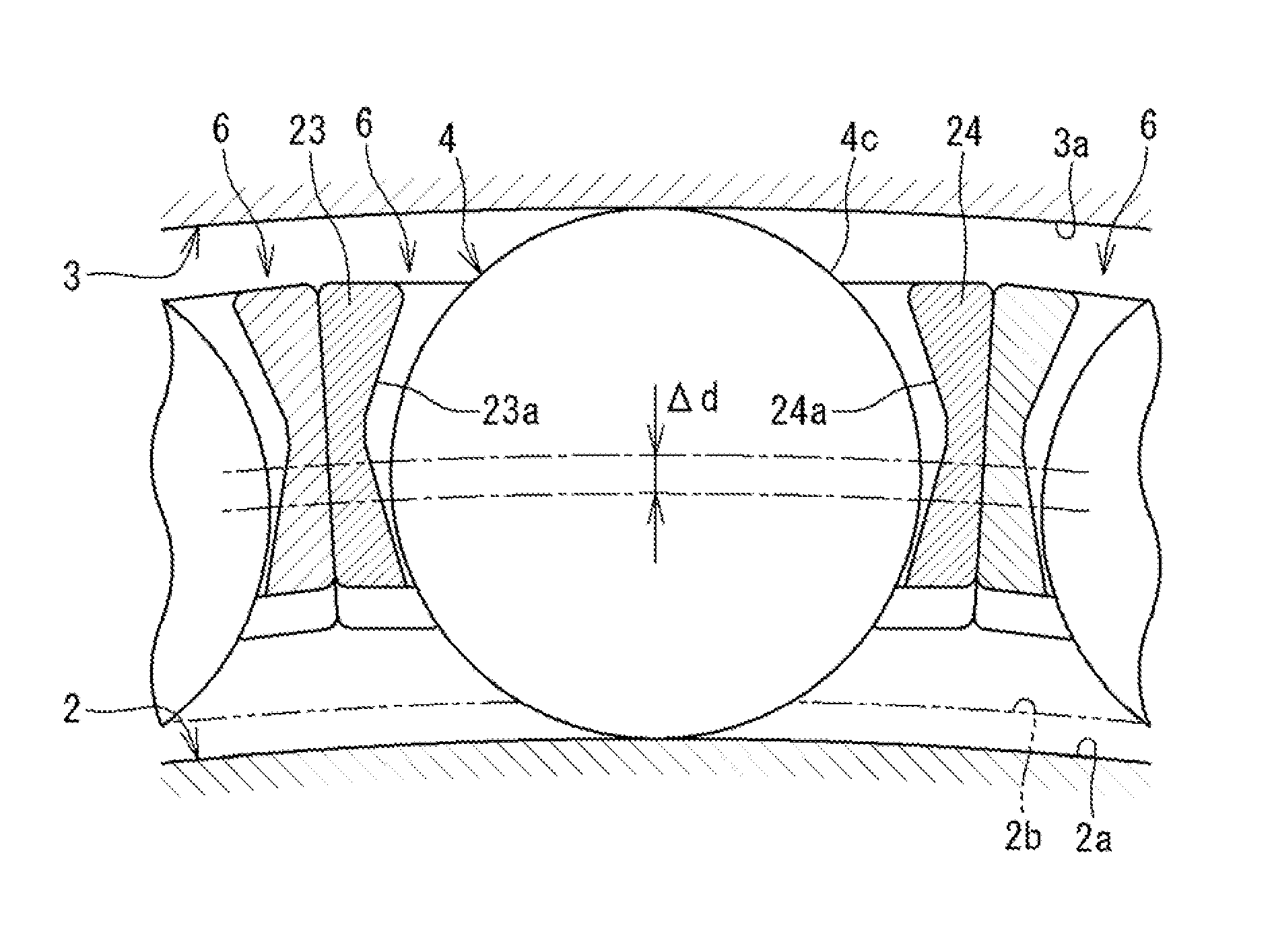
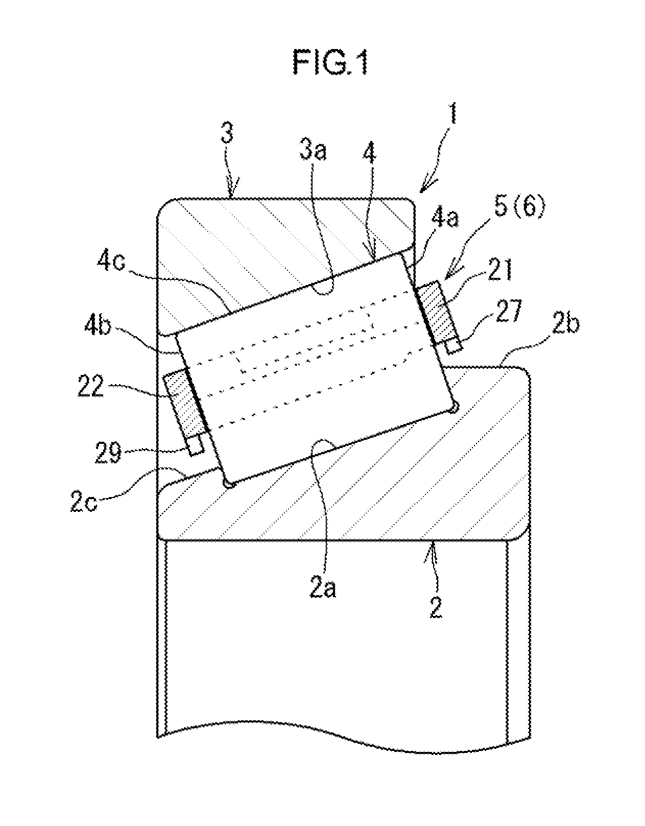
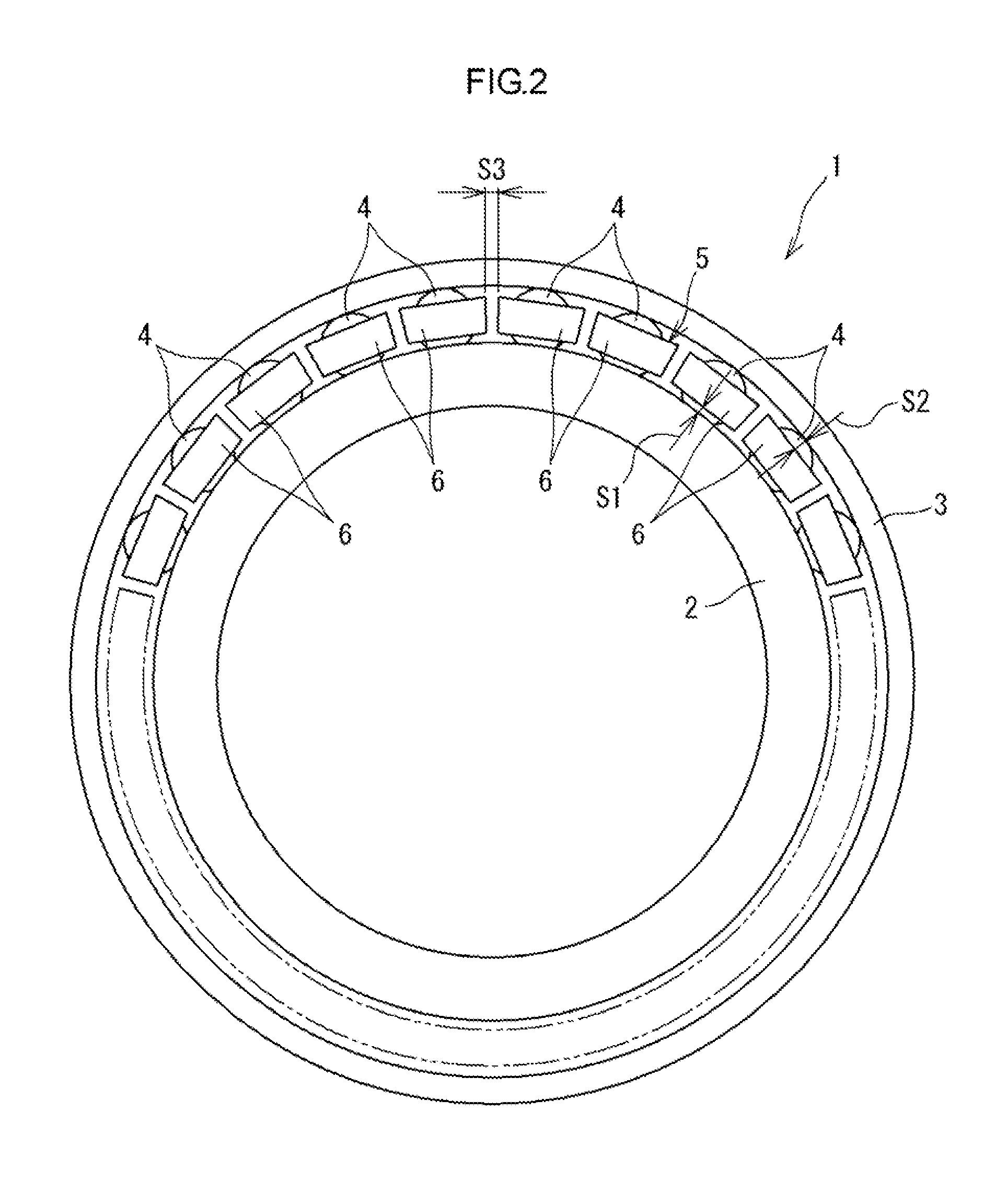
[0029]Hereinafter, example embodiments of the invention will be described in detail with reference to the accompanying drawings. FIG. 1 is a sectional view illustrating main portions of a tapered roller bearing 1 provided with a split cage 5 according to the invention. The tapered roller bearing 1 according to the present embodiment includes an inner ring 2, an outer ring 3, a plurality of tapered rollers 4 and the split cage 5. The tapered rollers 4 are rollably disposed in an annular space between the inner ring 2 and the outer ring 3. The split cage 5 holds the tapered rollers 4.

[0030]The inner periphery of the outer ring 3 has an outer ring raceway surface 3a, which is a tapered face, such that the tapered rollers 4 roll. The outer periphery of the inner ring 2 has an inner ring raceway surface 2a, which is a taped face, at such a position that the inner ring raceway surface 2a faces the outer ring raceway surface 3a such that the tapered rollers 4 roll. Lubricant such as grease...

second embodiment

[0047]FIG. 9 is a sectional view illustrating main portions of a tapered roller bearing 1 provided with a split cage 5 according to the invention. FIG. 10 is a perspective view illustrating one of cage segments 6 that constitute the split cage 5. In the cage segment 6 according to the present embodiment, first and third projections 26, 28 and second and fourth projections 27, 29 are formed so as to project from the radially inner face of the second cage bar portion 24 and the radially inner face of the first cage bar portion 23, respectively. Specifically, the second projection 27 and the fourth projection 29 that project radially inward are formed integrally with respective longitudinal (axial) end portions of the radially inner face of the first cage bar portion 23. Similarly, the first projection 26 and the third projection 28 that project radially inward are formed integrally with respective longitudinal (axial) end portions of the radially inner face of the second cage bar port...

third embodiment

[0052]FIG. 13 is a sectional view illustrating main portions of a tapered roller bearing 1 provided with a split cage 5 according to the invention. FIG. 14 is a perspective view illustrating one of cage segments 6 that constitute the split cage 5. In the cage segment 6 according to the present embodiment, first and third projections 26, 28 and second and fourth projections 27, 29 are formed so as to project from the radially outer face of the second cage bar portion 24 and the radially outer face of the first cage bar portion 23, respectively. Specifically, the second projection 27 and the fourth projection 29 that project radially outward are formed integrally with respective longitudinal (axial) end portions of the radially outer face of the first cage bar portion 23. Similarly, the first projection 26 and the third projection 28 that project radially outward are formed integrally with respective longitudinal (axial) end portions of the radially outer face of the second cage bar p...


PUM


Abstract

A split cage includes a plurality of cage segments, each of the cage segments having a pair of rim portions, and a pair of cage bar portions, the cage bar portions and the rim portions defining a pocket that accommodates a tapered roller. Turning of each of the cage segments is guided by the tapered roller, the cage segments being arranged in a circular pattern along the circumferential direction of the split cage, in an annular space between an inner ring and an outer ring. A radial clearance between a radially inner portion of a pocket-side face, which is a side face of each of the cage bar portions, and the outer peripheral face of the tapered roller is set larger than an amount of change in the pitch circle radius of the cage segment when the cage segment is displaced radially outward due to thermal expansion.

Description

INCORPORATION BY REFERENCE[0001]The disclosure of Japanese Patent Application No. 2013-242857 filed on Nov. 25, 2013 including the specification, drawings and abstract, is incorporated herein by reference in its entirety.BACKGROUND OF THE INVENTION[0002]1. Field of the Invention[0003]The invention relates to a split cage and a roller bearing.[0004]2. Description of the Related Art[0005]As a cage that holds a plurality of rollers, which roll between an inner ring and an outer ring of a roller bearing, at prescribed intervals along the circumferential direction of the cage, there is a conventional split cage formed of a plurality of cage segments arranged in a circular pattern along the circumferential direction and each having a single pocket that accommodates a single roller (refer to, for example, Japanese Patent Application Publication No. 2011-133061). As this type of split cage, there is often adopted a cage of a roller guidance type, of which the turning is guided by rollers in...

Claims


Application Information

Patent Timeline
Patent Type & Authority Patents(United States)
IPC IPC(8): F16C19/26F16C19/36F16C17/22F16C33/46F16C33/51F16C33/58F16C33/56
CPCF16C33/467F16C17/22F16C19/364F16C33/4605F16C33/4676F16C33/51F16C33/513F16C33/56F16C33/585F16C2202/22
Inventor YASUDA, HIROTAKA
Owner JTEKT CORP
Why Eureka
Try Eureka