Hydro vortex enabled turbine generator

a turbine generator and hydro vortex technology, applied in reaction engines, machines/engines, mechanical apparatuses, etc., can solve the problems of not working in water, system using no natural flow, not working in free flowing water, etc., to achieve the effect of not affecting or reducing the efficiency of the blade system, and high velocity

Active Publication Date: 2016-04-26
HALLETT MARTIN D
View PDF9 Cites 14 Cited by
  • Summary
  • Abstract
  • Description
  • Claims
  • Application Information

AI Technical Summary

Benefits of technology

[0060]A still yet further object of the present invention is to provide a Vortex Hydro Turbine having a tail pipe that allows a larger quantity of water or base amount of water to flow directly through the blade system from front to back of the unit thus allowing additional water flow through the blades over what the low pressure from the vortex alone provides.
[0061]Another object of the present invention is to provide a Vortex Hydro Turbine having a r...

Problems solved by technology

This system uses no natural flow and would not work in free flowing water.
The '077 patent discloses a motor and propeller to create and harness a vortex to improve the flow in the system, which uses no natural flow and theref...

Method used


Image

  • Hydro vortex enabled turbine generator
  • Hydro vortex enabled turbine generator
  • Hydro vortex enabled turbine generator

Examples


Embodiment Construction

[0104]The following discussion describes in detail one embodiment of the invention. This discussion should not be construed, however, as limiting the invention to those particular embodiments, practitioners skilled in the art will recognize numerous other embodiments as well. For definition of the complete scope of the invention, the reader is directed to appended claims.

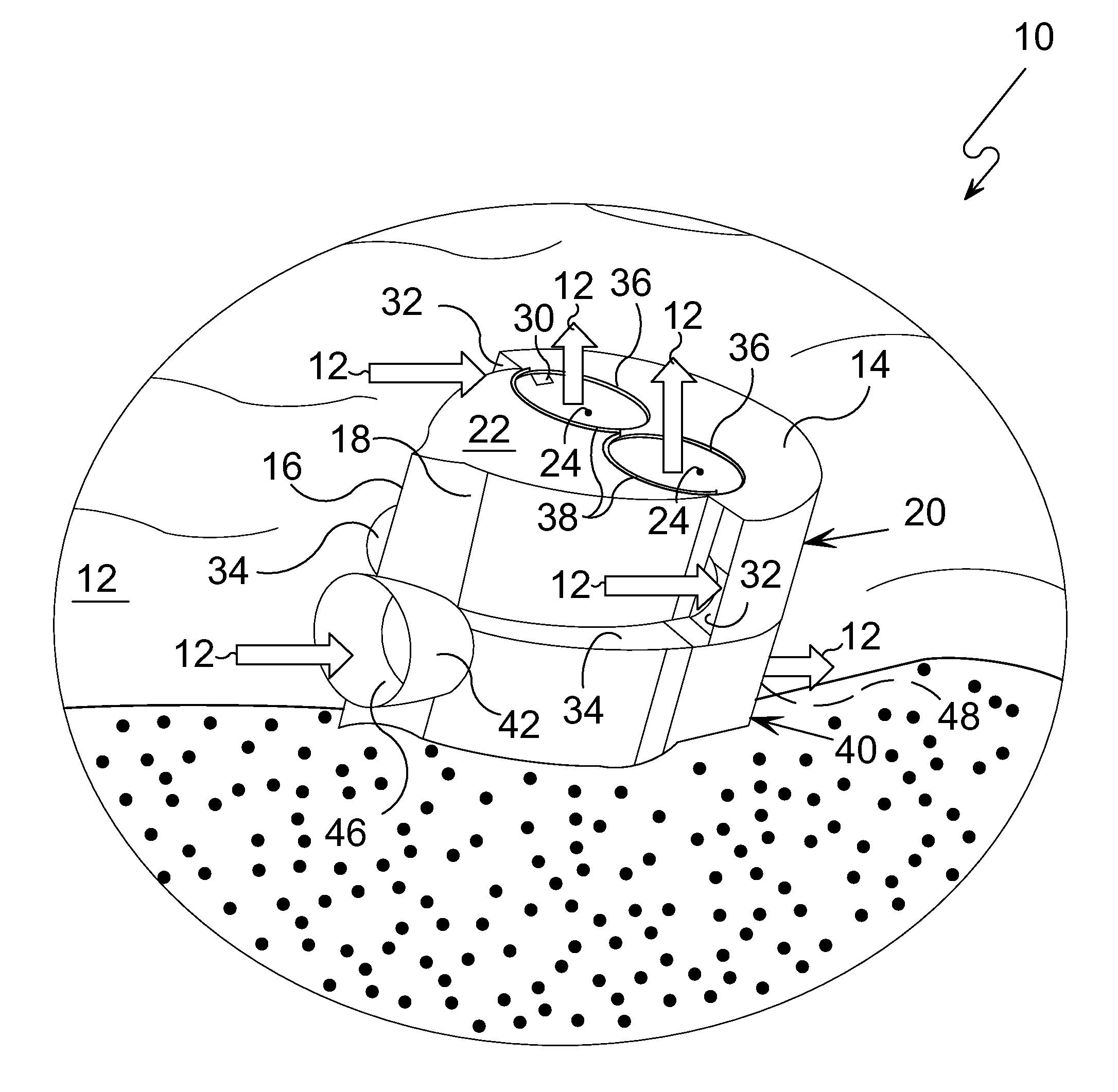
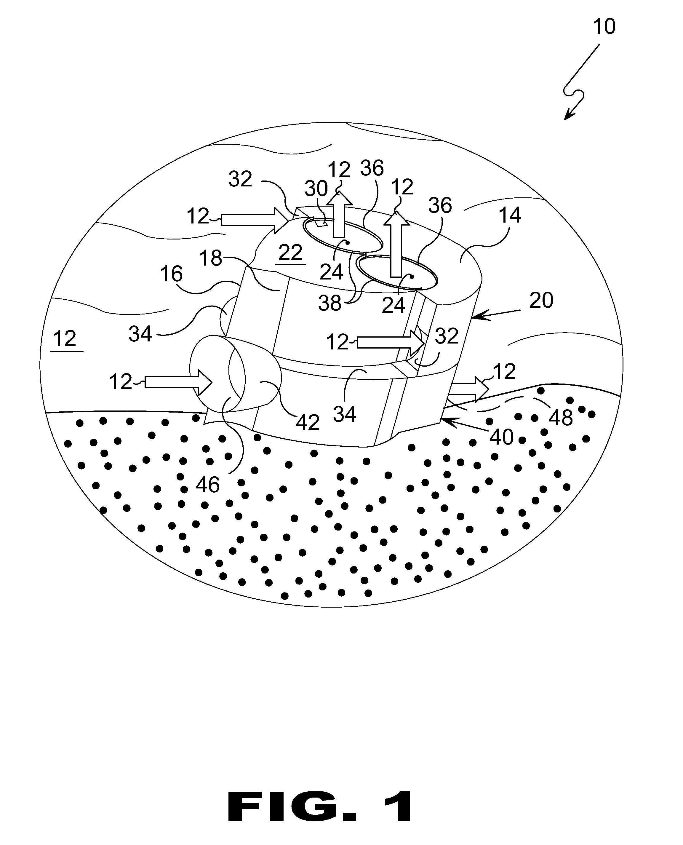
[0105]Referring to FIG. 1 shown is an illustrative view of the Vortex Hydro Turbine of the present invention in use. Depicted is an embodiment of the Vortex Hydro Turbine 10 comprising housing 14 having a vortex unit 20 and a turbine unit 40 positioned within a free flowing fluid 12 forming a working fluid that is partially channeled through the vortex unit 20 and partially through the turbine unit 40 with the vortex unit portion designed to impinge a low pressure state behind the turbine unit blades. The vortex unit 20 provides a pair of side mounted vortex intake ports 32 with sloped intakes 34 providing a vertica...


PUM


Abstract

The Vortex Hydro Turbine takes water through two upper inlets and one lower inlet from the current in which it is submerged. The upper inlets direct the water flow into cylindrical chambers with a spiral bottom to create a vortex. The top of the chambers are specifically left open to allow the water to exit and to reintegrate into the existing native flow. This movement of the water creates a low pressure area within the center of each of the chambers which is transferred to the back side of a turbine blade system through depending tubes. Water flows thru the turbine blade via the lower inlet and out the tail pipe. The low pressure from the depending tubes, aft of the blades, increases the water velocity through the blades for increased power output. The system can be scaled as a standalone unit or as an array.

Description

RELATED APPLICATIONS[0001]This application is a Continuation-In-Part of U.S. patent application Ser. No. 12 / 558,079, having a filing date 11 Sep. 2009.[0002]Please incorporate by reference all information in said provisional application into this instant application.BACKGROUND OF THE INVENTION[0003]1. Field of the Invention[0004]The present invention relates generally to turbines and, more specifically, to free stream hydro-kinetic energy.[0005]Depicted in the accompany drawings is an enablement of the aforementioned only for illustrative purposes in describing the instant invention.[0006]2. Description of the Prior Art[0007]There are other devices designed for using vortexes. Typical of these is U.S. Pat. No. 4,076,448 issued to Sanders, Jr. on Feb. 28, 1978.[0008]Another patent was issued to Erickson on Jul. 18, 1978 as U.S. Pat. No. 4,101,246. Yet another U.S. Pat. No. 4,452,046 was issued to Valentin on Jun. 5, 1984 and still yet another was issued on Jun. 5, 1984 to Hsu as U.S....

Claims


Application Information

Patent Timeline
IPC IPC(8): F03B13/12F03B3/02F03B3/18F03B11/02
CPCF03B3/186F03B3/02F03B11/02F03B17/061F05B2210/402F05B2240/122F05B2240/13F05B2240/132Y02E10/30Y02E10/20
Inventor HALLETT, MARTIN D.
Owner HALLETT MARTIN D
Why Eureka
Try Eureka