
Radiation imaging apparatus, method for controlling the same, and radiation image detection device

a technology of radiation imaging apparatus and control method, which is applied in the field of radiation imaging apparatus, can solve the problems of inability to perform synchronous control using communication method, inability to detect rises and falls of x-ray pulses, and inability to achieve synchronous control. , to achieve the effect of avoiding cost increase and complicated operation

Active Publication Date: 2016-04-26
FUJIFILM CORP
View PDF7 Cites 8 Cited by
  • Summary
  • Abstract
  • Description
  • Claims
  • Application Information

AI Technical Summary

Benefits of technology

The present invention provides a radiation imaging apparatus, method, and radiation image detection device that can appropriately control its operation based on the irradiation profile of the radiation generating apparatus, without compromising its cost-effectiveness and ease-of-use. This allows for optimal performance even when using a radiation imaging apparatus in combination with a radiation generating apparatus that cannot communicate. The technical effect of this invention is improved efficiency and reliability in radiation imaging procedures, especially in the context of fluoroscopy.

Problems solved by technology

However, it is impossible to perform the synchronous control using the communication method if the X-ray generating apparatus does not have a communication function.
However, the synchronous control has certain limits.
In this case, the detection of the rises and the falls of the X-ray pulses and the synchronous control may not be feasible, depending on the type of the pulse detecting means.
However, the X-ray generating apparatus comprising the X-ray tube with the fast response speed is expensive, which increases replacement cost.
Even if such X-ray generating apparatus is used, the self detection may not be allowed in a case where a frame rate of the fluoroscopy is extremely short.
Thus, in some cases, the synchronous control is not feasible.
However, the calculation of the overlapping state of the X-ray pulses by an operator is extremely complicated and not practical because the calculation must be done in accordance with the tube current and the tube voltage which are changed per image capture even if the same X-ray tube is used.
Even if the X-ray tube with the fast response speed is used or the operator calculated the overlapping state of the X-ray pulses, an additional measure is necessary in a case where the synchronous control is not feasible.

Method used


Image

  • Radiation imaging apparatus, method for controlling the same, and radiation image detection device
  • Radiation imaging apparatus, method for controlling the same, and radiation image detection device
  • Radiation imaging apparatus, method for controlling the same, and radiation image detection device

Examples


Embodiment Construction

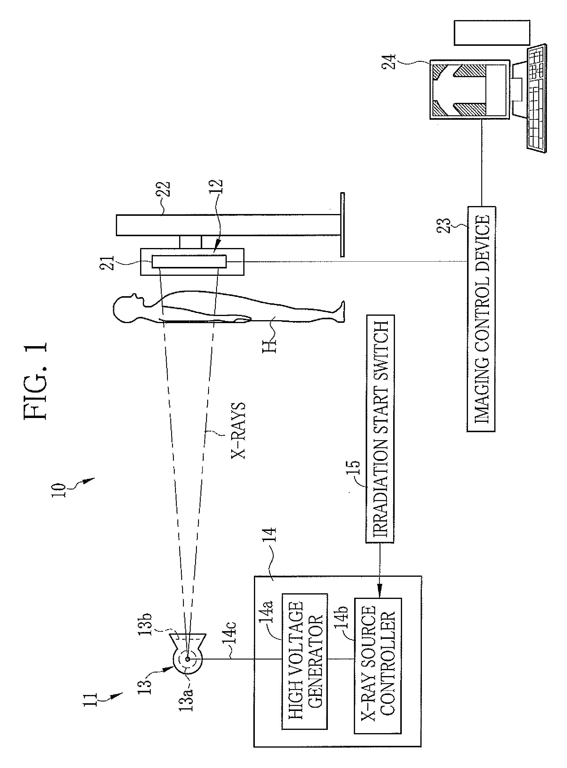
[0055]In FIG. 1, an X-ray imaging system 10 comprises an X-ray generating apparatus 11 and an X-ray imaging apparatus 12. The X-ray generating apparatus 11 is, for example, a conventional X-ray generating apparatus employed for a film cassette or an IP cassette, and is not equipped with a communication function to communicate with the X-ray imaging apparatus 12. The X-ray generating apparatus 11 is composed of an X-ray source 13, an X-ray source control device 14 for controlling the X-ray source 13, and an irradiation start switch 15. The X-ray source 13 has an X-ray tube 13a and a collimator 13b. The X-ray tube 13a emits X-rays. The collimator 13b defines and restricts an X-ray field of the X-rays emitted from the X-ray tube 13a.

[0056]The X-ray tube 13a has a cathode and an anode (target). The cathode is composed of a filament that releases thermoelectrons. The thermoelectrons released from the cathode collide against the anode and thereby the anode emits X-rays. The collimator 13...


PUM


Abstract

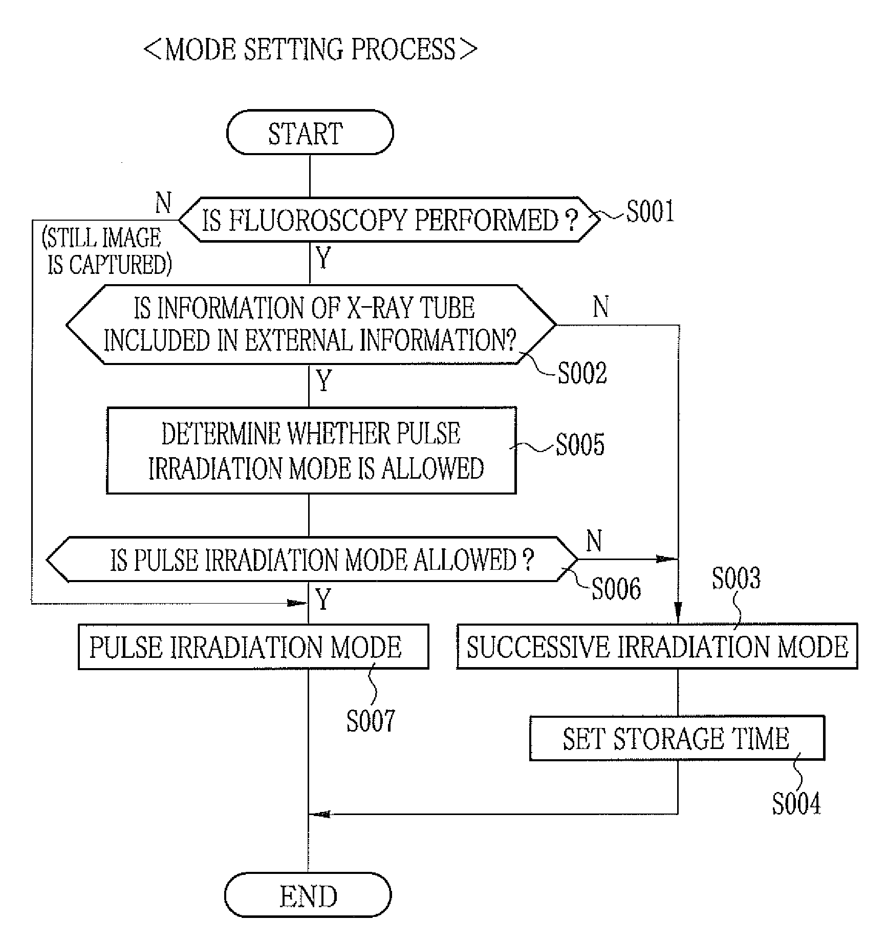
A determination section of an FPD checks external information against a determination table and determines whether detection of a rise of X-ray pulses is allowed based on an output voltage from a short-circuited pixel. The FPD detects X-ray images. The external information is transmitted from an imaging control device. The X-ray pulses are sequentially generated by an X-ray generating apparatus. A controller selects a pulse irradiation mode in a case where the detection of the rise of the X-ray pulse is allowed. If not, a successive irradiation mode is selected. In the pulse irradiation mode, the rise and the fall of the X-ray pulse are detected and timing of storage operation is synchronized with the detected timing of the rise. In the successive irradiation mode, the storage operation is performed at predetermined time intervals without the detection of the rise and the fall of the X-ray pulse.

Description

BACKGROUND OF THE INVENTION[0001]1. Field of the Invention[0002]The present invention relates to a radiation imaging apparatus for capturing a radiation image of an object, a method for controlling the same, and a radiation image detection device.[0003]2. Description Related to the Prior Art[0004]In the medical field, a radiation imaging system using radiation, for example, X-rays is known. An X-ray imaging system comprises an X-ray generating apparatus and an X-ray imaging apparatus. The X-ray generating apparatus comprises an X-ray tube for generating the X-rays. The X-ray imaging apparatus comprises an X-ray image detection device and peripheral devices such as an imaging control device and a console. The X-rays passed through an object is incident on the X-ray image detection device and thereby the X-ray image detection device detects an X-ray image representing image information of the object. The imaging control device controls the X-ray image detection device. Imaging conditi...

Claims


Application Information

Patent Timeline
Patent Type & Authority Patents(United States)
IPC IPC(8): A61B6/00H04N5/32G01T1/16H04N5/353H04N5/374
CPCG01T1/16A61B6/4233A61B6/4283H04N5/32A61B6/54H04N5/353H04N5/374H04N25/76H04N23/30H04N25/532H04N25/53
Inventor IWAKIRI, NAOTONISHINO, NAOYUKIOHTA, YASUNORIKITANO, KOUICHINAKATSUGAWA, HARUYASU
Owner FUJIFILM CORP
Learn More