
Heart rate extraction using neural wavelet adaptive gain control and neural pattern processing

a neural wavelet adaptive gain control and heart rate technology, applied in the field of heart rate monitors, can solve the problems of requiring amplification, affecting the accuracy of heart rate signals, and easy saturation of amplifiers, so as to eliminate large noise components, avoid saturating the system, and eliminate noise components.

Active Publication Date: 2016-05-24
SCHIE DAVID +1
View PDF1 Cites 8 Cited by
  • Summary
  • Abstract
  • Description
  • Claims
  • Application Information

AI Technical Summary

Benefits of technology

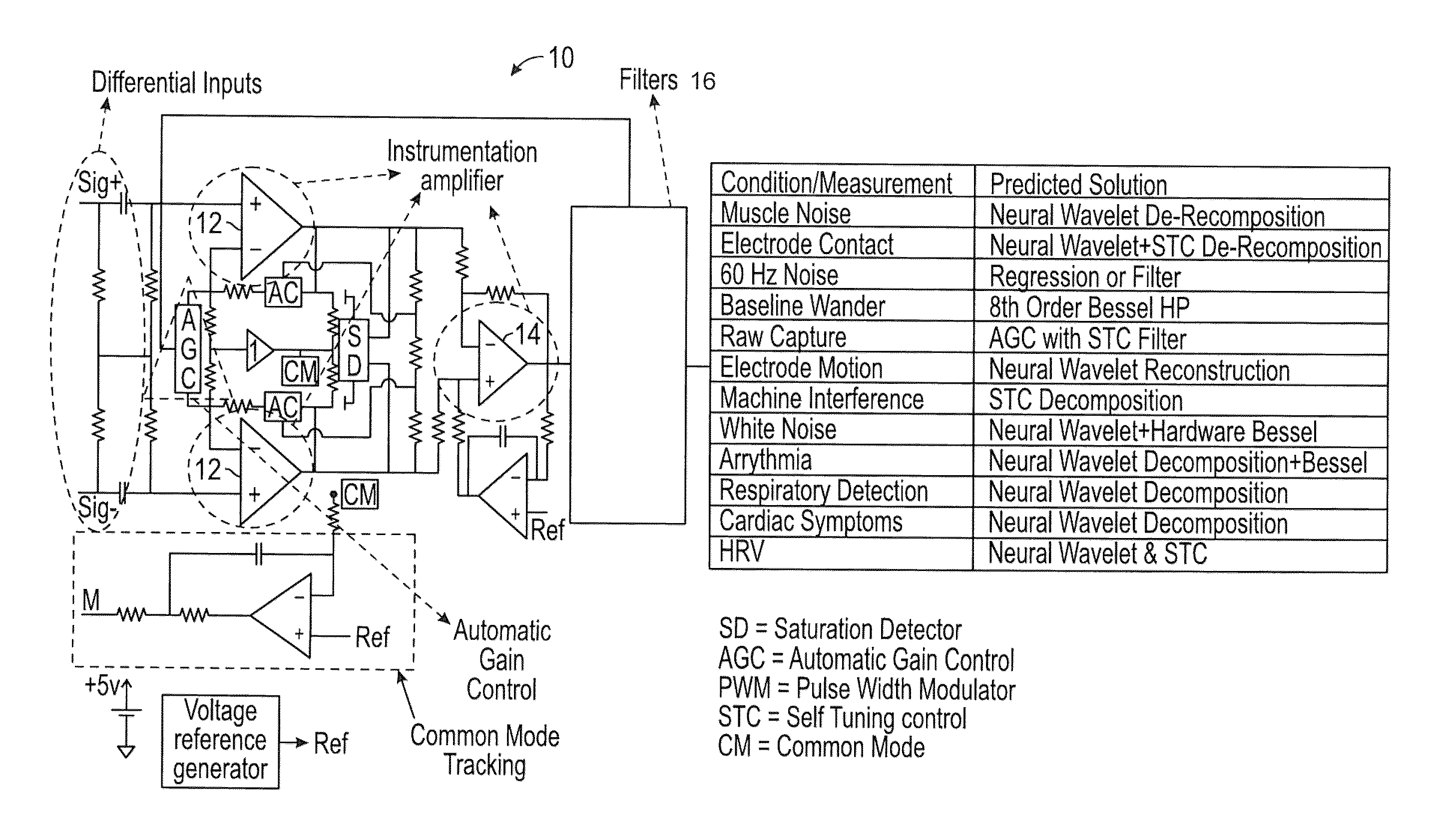
[0005]An improved heart rate monitor is provided that can detect and distinguish a heartbeat from an otherwise contaminated system with noise components potentially larger than the signal of interest (and / or in the same frequency band). Embodiments of the inventive monitor have an amplification system that eliminates large noise components so as not to saturate the system during detection of a desired low amplitude signal. In embodiments the elimination of noise components is accomplished through wavelet decomposition, and the removal of undesired components including interference components during adaptive gain control (AGC), in addition to hunting algorithms which minimize the error with techniques such as neural network least mean squares type back (and / or feedforward) propagation algorithms.
[0006]Embodiments of the inventive heart rate monitor provide a method that improves correlation with a wavelet by creating a unique wavelet family which resonates specifically with the PQRST (P wave, QRS complex, T wave, where P wave represents atrial depolarization, QRS represents ventricular depolarization, and T wave reflects the phase of rapid repolarization of the ventricles) components of a basic electrocardiogram (ECG), but which otherwise follows the rigorous mathematical conditions for a wavelet including stability. In embodiments, wavelet decomposition is used in conjunction with a feedback network around the input stage amplifiers, which may be an analog or digital feedback network, to eliminate wavelet components which are caused by interference components, and which otherwise might saturate the detection system.
[0007]Embodiments of the present invention capture a signal utilizing a high common-mode rejection ratio (CMRR) termination, which does not include a DC path or load the probes. Additionally in embodiments, an instrumentation amplifier is broken into several parts which include an optional common mode driver, common mode accelerator, and an active feedback network, which could be an analog feedback network or a digital feedback network. An electronically controlled variable resistor on the input stage to the amplifier allows the gain of the system to be altered by the AGC algorithm, while an analog or digital feedback network around the input amplifiers allows decomposition and removal of unwanted signals that might otherwise saturate the detector.
[0008]In embodiments, a saturation detector, which can accelerate the time constant of the system, allows the system to recover quickly from saturated conditions if they do occur. Circuitry to create the common mode may optionally be buffered to drive an electrode, which drives the subject to a potential between the placement of the two differential input electrodes, which are placed over the skin far enough away to allow sufficient impedance for a differential measurement. The common mode driving circuitry has a low enough current (typically <10 mA) to ensure it does not create discomfort in a user being monitored.

Problems solved by technology

Unfortunately devices which measure heart rate presently require electrodes on multiple parts of the body, or a location near the heart on the chest, and are cumbersome, especially for women.
Furthermore, heart rate signals on the arm are extremely small and require amplification, and the amplifiers may be easily saturated by interference components such as muscle movement, 60 Hz noise radiation from lighting or other equipment, respiration, electrode connection and disconnection during activity, baseline wander, or other sources of interference.

Method used


Image

  • Heart rate extraction using neural wavelet adaptive gain control and neural pattern processing
  • Heart rate extraction using neural wavelet adaptive gain control and neural pattern processing
  • Heart rate extraction using neural wavelet adaptive gain control and neural pattern processing

Examples


example

Checking Admissibility Condition for Haar MRA:

[0108]Expression for Haar wavelet:

[0109]ψ^⁡(ω)=sin2⁢ω / 4ω / 4

[0110]Applying admissibility condition:

[0111]∫0∞⁢ψ^⁡(ω)2⁢ⅆωω=∫0∞⁢sin4⁡(ω / 4)(ω / 4)2⁢⁢ⅆωω

[0112]The integral can be expressed as:

[0113]∫0∞⁢=∫0∂⁢+∫∂∞

[0114]For integral

[0115]∫0∂⁢sin2⁢λ / 4λ / 42⁢⁢ⅆλλ≤∫0∞⁢λ / 42⁢⁢ⅆλλ=∫0∞⁢λ16⁢⁢ⅆλ⁡(∵sin⁢⁢λ≤λ)

[0116]which converges as ∂→0.

[0117]Also the integral

[0118]∫∂∞⁢sin2⁢λ / 4λ / 42⁢⁢ⅆλλ<∫∂∞⁢16λ3

(∵ sin λ<1) therefore as ∂→∞ the integral converges.

[0119]Hence Haar wavelet satisfies admissibility condition.

Inverse Continuous Wavelet Transform (ICWT)

[0120]From Parseval theorem, to get inverse wavelet transform choose y(t) to be an unit area narrow pulse around t=t0 (or as impulse)

[0121]x⁡(t0)=Kψ⁢∫∫Wψ⁢x⁡(b,a)⁢ψ⁡(t0-ba)⁢ⅆb⁢ⅆaa2[0122]where again

[0123]Kψ=∫ψ^⁡(λ)2⁢ⅆλλ;[0124] a constant on the condition that

[0125]∫ψ^⁡(ω)2⁢ⅆωω[0126] converges i.e. ADMISSIBILITY CONDITION.

[0127]It is because of admissibility, that the CWT is invertible.

[0128]If spectrum of ψ(t) i.e. {cir...


PUM


Abstract

An improved heart rate monitor is provided that can detect and distinguish a heartbeat from an otherwise contaminated system with noise components potentially larger than the signal of interest. Embodiments of the inventive monitor have an amplification system that eliminates large noise components so as not to saturate the system during detection of a desired low amplitude signal. In embodiments the elimination of noise components is accomplished through wavelet decomposition, and the removal of undesired components including interference components during adaptive gain control (AGC), in addition to hunting algorithms which minimize the error with techniques such as neural network least mean squares type back propagation algorithms.

Description

CROSS-REFERENCE TO RELATED APPLICATION[0001]This application claims priority of U.S. Provisional Patent Application Ser. No. 61 / 682,271 filed Aug. 12, 2012, which is incorporated herein by reference.FIELD OF THE INVENTION[0002]The present invention in general relates to heart rate monitors, and more particularly, to a heart rate monitor that can detect and distinguish a heartbeat from an otherwise contaminated system with noise components potentially larger than the signal of interest.BACKGROUND OF THE INVENTION[0003]Heart rate monitors are popular in fitness and other applications which require the monitors to have size and form factors which do not interfere with the activity of the user being monitored. Unfortunately devices which measure heart rate presently require electrodes on multiple parts of the body, or a location near the heart on the chest, and are cumbersome, especially for women. Furthermore, heart rate signals on the arm are extremely small and require amplification,...

Claims


Application Information

Patent Timeline
Patent Type & Authority Patents(United States)
IPC IPC(8): A61B5/0452A61B5/04A61B5/0245A61B5/00
CPCA61B5/04017A61B5/726A61B5/7207A61B5/7264A61B5/0006A61B5/0022A61B5/0245A61B5/0452A61B5/316A61B5/349G16H50/20
Inventor SCHIE, DAVIDWARD, MIKE
Owner SCHIE DAVID
Learn More