

Affixation of objects to garments
- Summary
- Abstract
- Description
- Claims
- Application Information
AI Technical Summary
Benefits of technology
Problems solved by technology
Method used
Image

Examples
Embodiment Construction
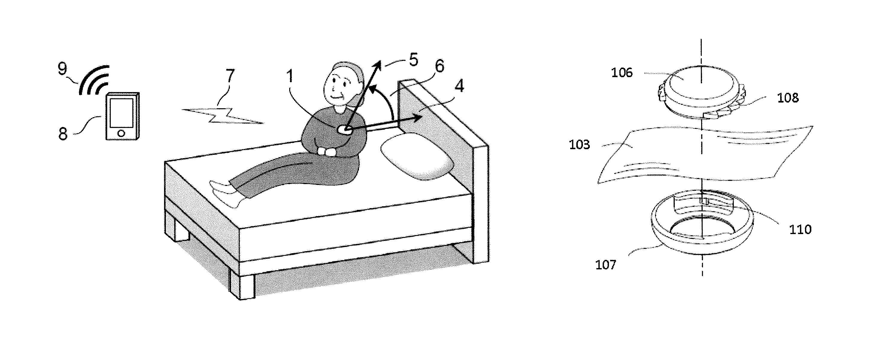
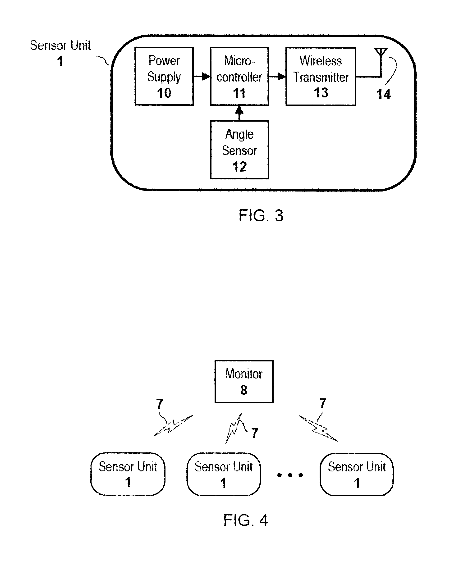
[0059]In general, described herein are methods and apparatuses for attaching one or more sensors to a subject's body. For example a sensor (e.g., devices such as angle-sensing units and systems including one or more angle-sensing units and / or one or more monitoring unit) can determine a change in gross body angle indicating that a subject wearing the device has gotten up and / or out of a bed, and in some variations a chair. Also described herein are apparatuses and methods for safely, securely, and detachably affixing objects (such as the angle-sensing units described herein) to clothing.
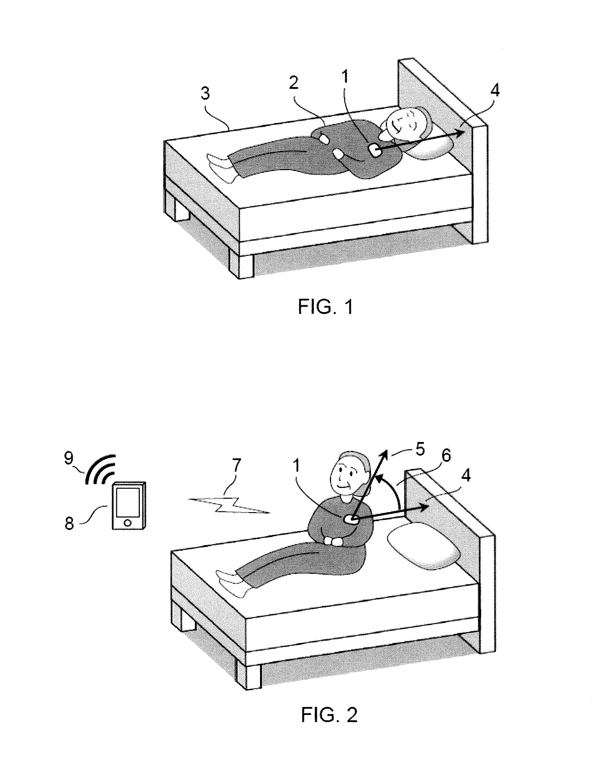
[0060]For example, FIG. 1, schematically illustrates operation of one variation of an angle-sensing unit. In FIG. 1, a subject 2 is shown lying down on a bed 3 wearing an angle-sensing unit 1 on his or her body. In general, the angle-sensing unit can be directly adhered to the subject's body, or affixed on the clothes, pajama, briefs, a belt or an accessory worn by the subject. The unit may be tightl...
PUM
 Abstract
Description
Claims
Application Information