Microactuator bonding having increased adhesive exposure for more thorough adhesive cure

a microactuator and bonding technology, applied in the direction of magnetic recording, instruments, data recording, etc., can solve the problems of insufficient curing of conductive epoxy b>50/b>, which can produce grounding degradation or even failure during epoxy fatigue reliability testing, and achieves the effect of improving the quality of conductive epoxy bonding and resistance ground connection

Active Publication Date: 2016-05-24
MAGNECOMP
View PDF20 Cites 0 Cited by
  • Summary
  • Abstract
  • Description
  • Claims
  • Application Information

AI Technical Summary

Benefits of technology

[0017]The inventors have invented a new structure and method for electrically bonding the PZT to the stainless steel that produces more complete curing of the conductive epoxy, and hence a higher quality and more robust electrical contact.
[0020]This departure from the prior design is counterintuitive because the ground connection now has a longer run to make through the conductive epoxy. Upon first examination that design change would appear to create a higher resistance ground connection than before. However, because that conductive epoxy is now directly accessible by the heated air stream (or other curing exposure such as UV curing) during the epoxy cure step, that conductive epoxy can now be heated more completely during that step and thus the quality of that conductive epoxy bridge is improved, decreasing the possibility of a poor quality connection or even a complete failure of that bond over time and environmental conditions such as temperature cycling and vibration.

Problems solved by technology

Inadequate curing of conductive epoxy 50 can produce grounding degradation or even failure during epoxy fatigue reliability testing.

Method used


Image

  • Microactuator bonding having increased adhesive exposure for more thorough adhesive cure
  • Microactuator bonding having increased adhesive exposure for more thorough adhesive cure
  • Microactuator bonding having increased adhesive exposure for more thorough adhesive cure

Examples


first embodiment

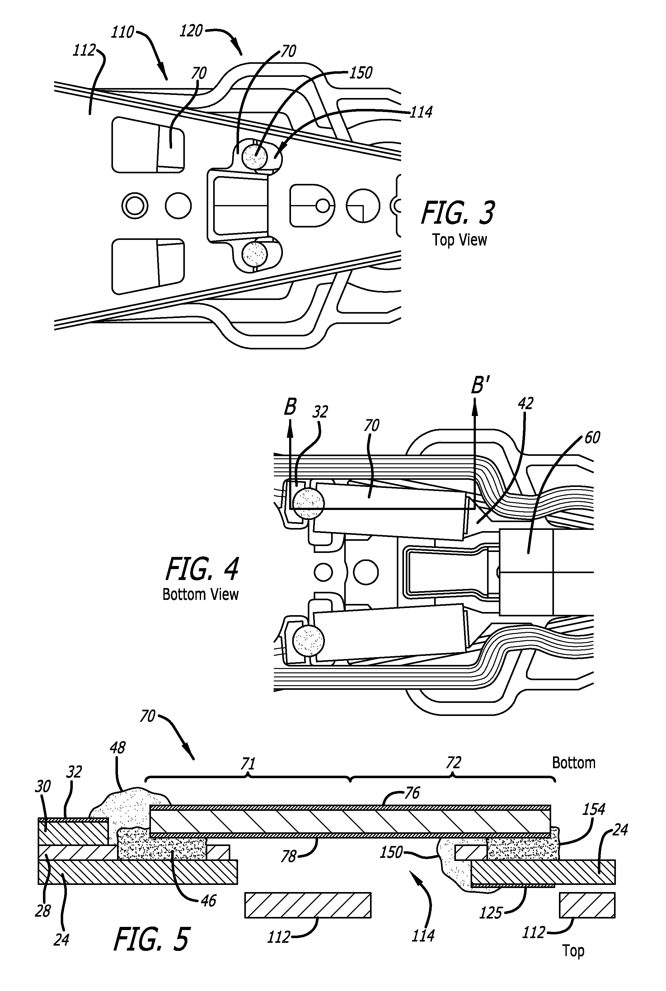
[0036]FIG. 3 is a top plan view of a GSA suspension 110 of the invention and FIG. 4 is a bottom plan view thereof. Load beam 112 has been modified to provide an aperture 114 therein so that the new ground electrical connection 150 can be accessed for curing such as by directing a stream of hot air onto it for a thermally curing epoxy, or by shining UV light onto it for a UV-curing epoxy, or other exposure for other types of curing depending on the type of electrically conductive adhesive employed.

[0037]FIG. 5 is a sectional view of the GSA suspension of FIG. 4, taken along section line B-B′. In the figures, the PZT grounding has been modified. Specifically, the electrical bridge of conductive epoxy 150 that defines the grounding bridge at distal end 72 of PZT 70 is applied through the aperture or opening 114 in load beam 112 to create the electrical connection between the PZT top electrode 78 and a gold plating layer that defines a gold plated grounding pad 125 on the top surface o...

third embodiment

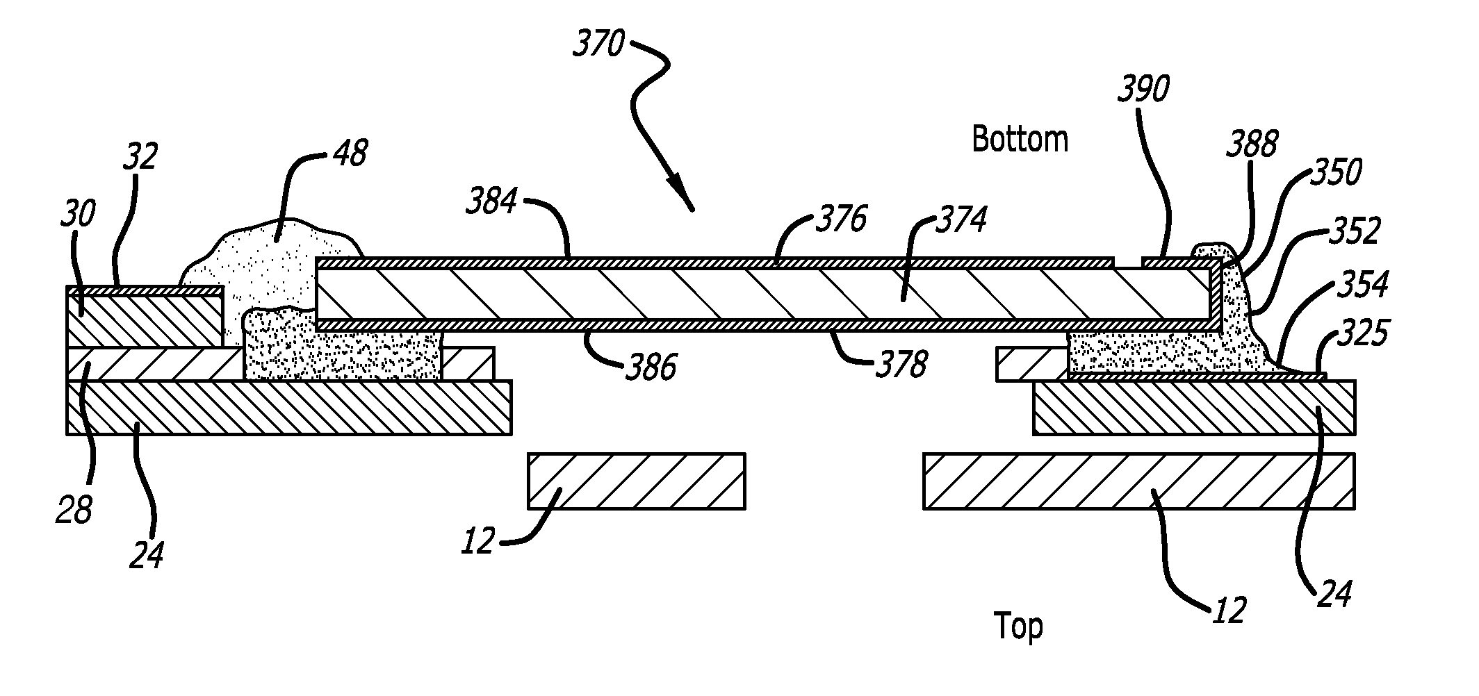
[0046]FIG. 10 is a sectional view of a third embodiment that employs a PZT 370 having a wrap-around electrode. PZT 370 has a PZT element 374, a bottom metalized surface 376 covering a majority 384 of its bottom surface and defining a first and driven electrode, and a second and ground electrode 378 that includes both a top surface 386 and either a side end 388 of PZT 370 and / or minority portion 390 of the PZT's bottom surface. As used herein, the term “wrap-around electrode” means an electrode that electrically extends from a first face to at least either the side end of the device, or to an opposite face of the device, or both. PZTs having such wrap-around electrodes are generally well known. Recent improvements in such devices and in methods of manufacturing such devices, and which could be employed in this embodiment, are disclosed in U.S. Pat. No. 8,773,820 issued to Hahn et al. and pending U.S. application Ser. No. 14 / 316,633 by Hahn et al., both assigned to the assignee of the...


PUM

PropertyMeasurementUnit
conductiveaaaaaaaaaa
hardenable conductiveaaaaaaaaaa
track densitiesaaaaaaaaaa

Abstract

In a dual stage actuated suspension, conductive adhesive is both sandwiched between a microactuator and a grounded stainless steel layer of the suspension, and also extends at least partially onto a wrap-around portion of the microactuator's ground electrode. The conductive adhesive that extends onto the wrap-around portion of the electrode has an exposed edge for more complete exposure and curing during the cure step.

Description

CROSS-REFERENCE TO RELATED APPLICATIONS[0001]This application is a divisional of U.S. application Ser. No. 14 / 472,820 filed Aug. 29, 2014, which claims the benefit of U.S. provisional patent application No. 61 / 873,809 filed Sep. 4, 2013.BACKGROUND OF THE INVENTION[0002]1. Field of the Invention[0003]This invention relates to the field of suspensions for disk drives. More particularly, this invention relates to the field of structures and methods for grounding a microactuator to a suspension in a dual stage actuated (DSA) suspension.[0004]2. Description of Related Art[0005]As the track densities of hard disk drives (HDDs) continue to increase, the need to position the data read / write head over the spinning disk platter quickly and accurately has likewise increased. Dual stage actuated (DSA) suspensions have been developed in order to accommodate the demand for more expedient and accurate positioning of the read / write head.[0006]In a DSA suspension, as for example in U.S. Pat. No. 7,4...

Claims


Application Information

Patent Timeline
Patent Type & Authority Patents(United States)
IPC IPC(8): G11B5/48G11B5/55
CPCG11B5/483G11B5/5552G11B5/4826G11B5/4853G11B5/4873
Inventor EE, KUEN CHEEHAHN, PETERZHANG, LONG
Owner MAGNECOMP
Why Eureka
Try Eureka