Method and apparatus for detecting logical signal

a logical signal and detection method technology, applied in the field of detection of logical signals, can solve the problems of deteriorating signal integrity and adversely increasing the probability of data detection error by the data detector, and achieve the effect of improving the resolution of a logical signal

Active Publication Date: 2016-05-24
REALTEK SEMICON CORP
View PDF8 Cites 2 Cited by
  • Summary
  • Abstract
  • Description
  • Claims
  • Application Information

AI Technical Summary

Benefits of technology

[0010]An objective of the present invention...

Problems solved by technology

Said parasitic capacitances introduce inter-symbol interference and degrades signal integrity for th...

Method used


Image

  • Method and apparatus for detecting logical signal
  • Method and apparatus for detecting logical signal
  • Method and apparatus for detecting logical signal

Examples


Embodiment Construction

[0026]The present invention generally relates to reception of logical signal and more particularly to a system that can improve the quality or resolution of the logical signal. While the specification describes several example embodiments of the invention considered favorable modes of practicing the invention, it should be understood that the invention can be implemented in many ways and is not limited to the particular examples described below or to the particular manner in which any features of such examples are implemented. In other instances, well-known details are not shown or described to avoid obscuring aspects of the invention.

[0027]In this disclosure, a logical signal is a signal of two states: “high” and “low,” which can also be re-phrased as “1” and “0.” For brevity, when a logical signal is in the “high” (“low”) state, it can be simply stated that the logical signal is “high” (“low”), or alternatively, the logical signal is “1” (“0”). Also, for brevity, sometimes the quo...


PUM


Abstract

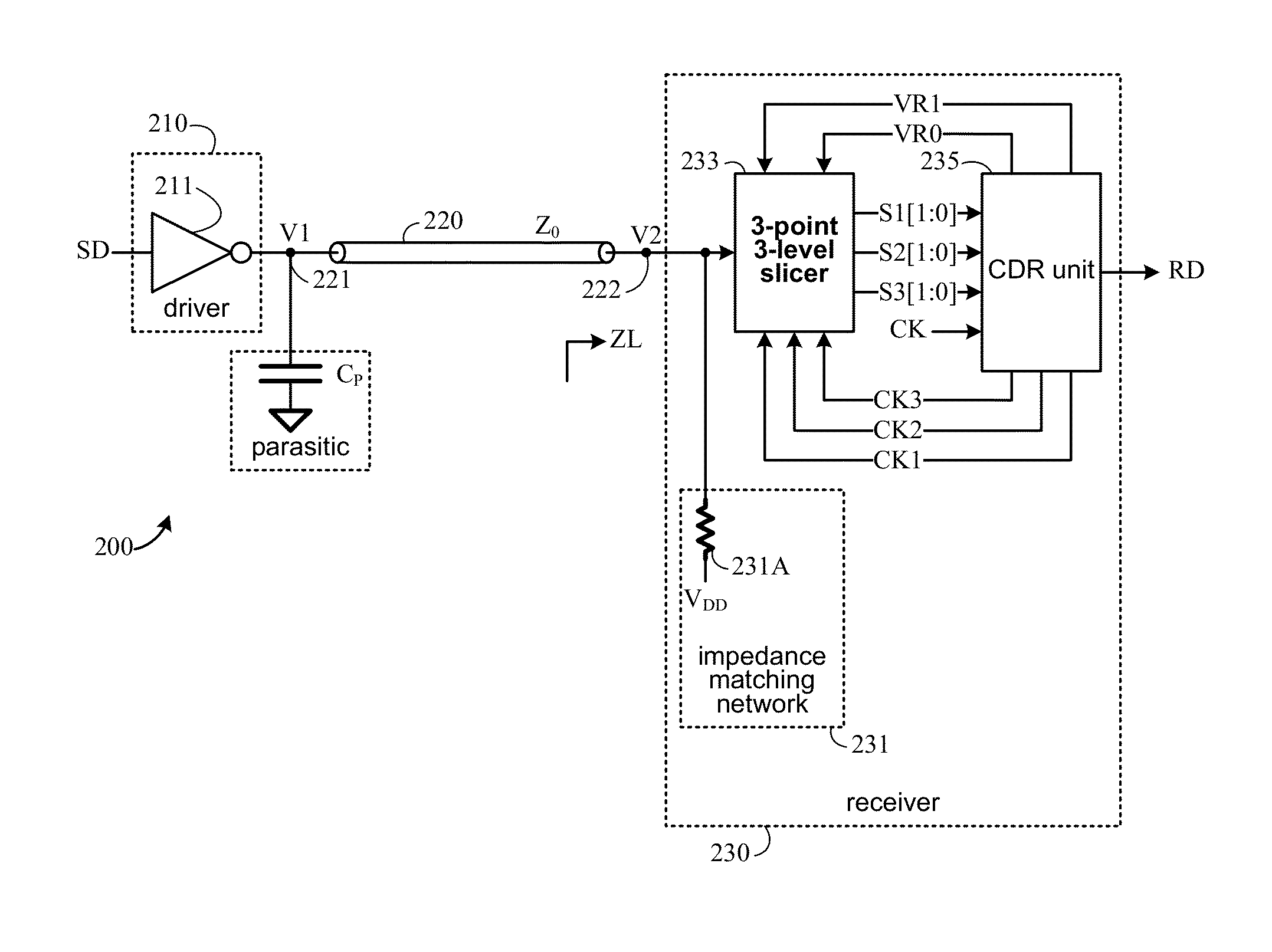
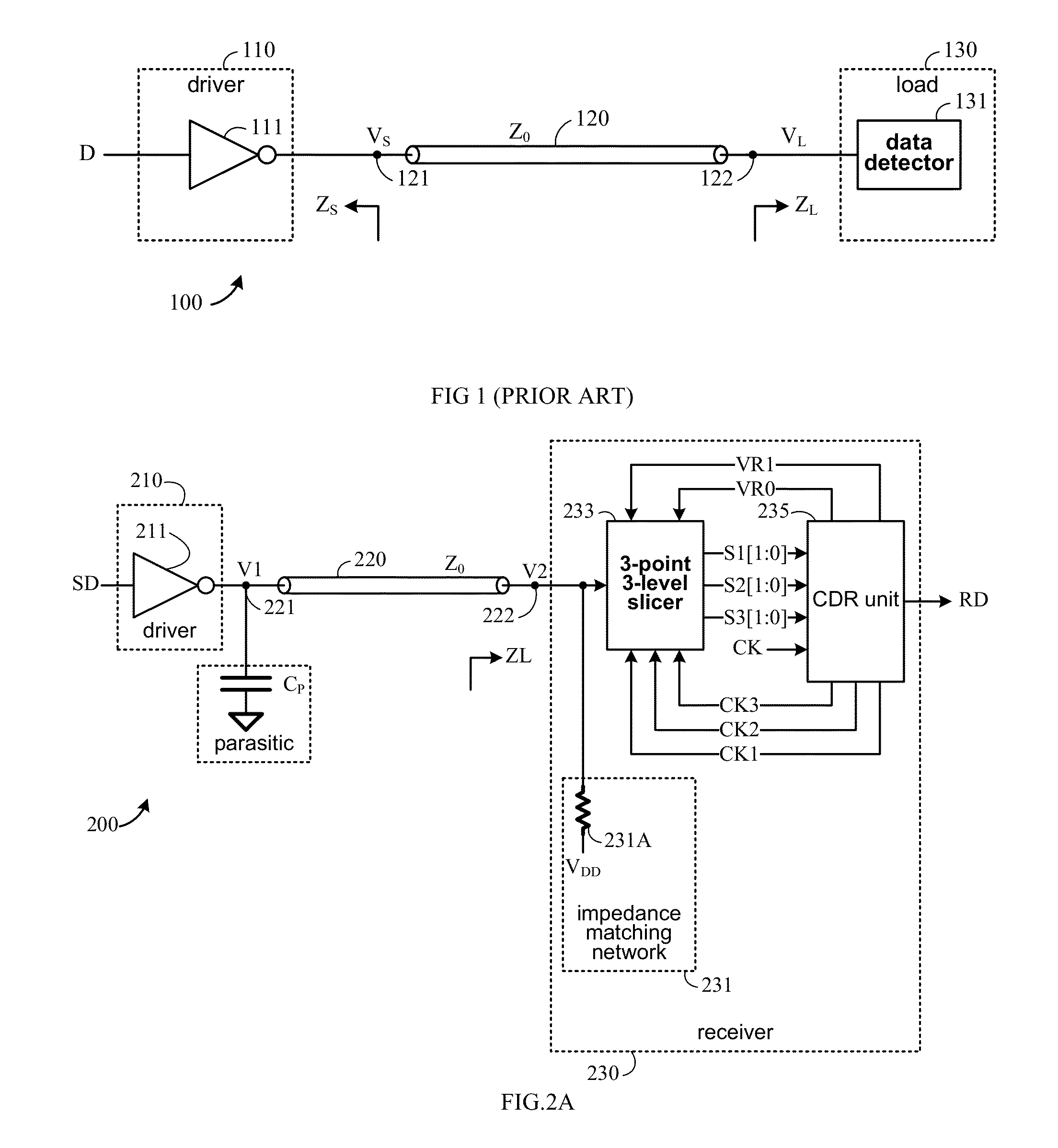
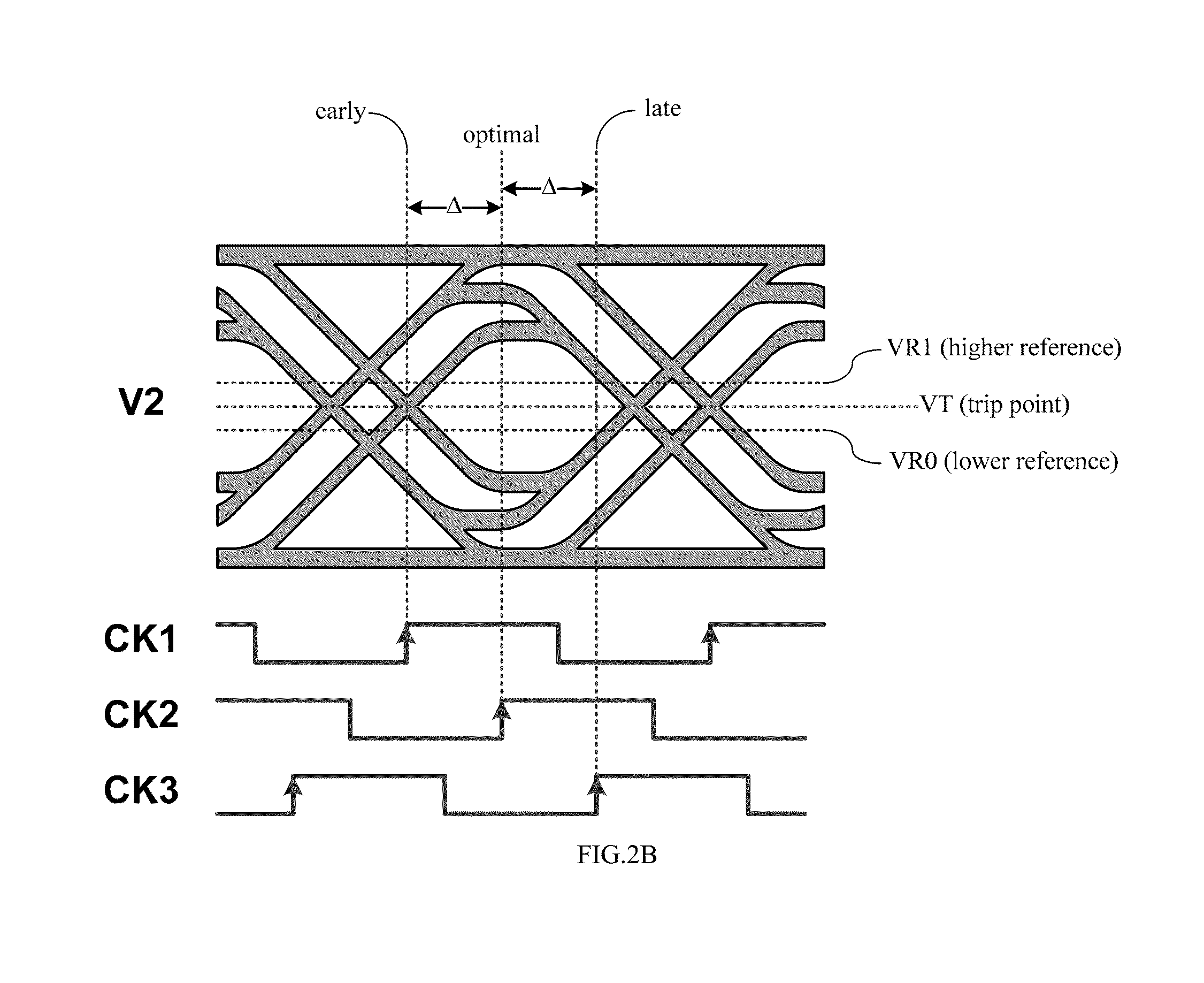
A logical transmission system includes a driver configured to receive a source data and output a first voltage at a first node; a transmission line of a characteristic impedance configured to couple the first node to a second node; a three-point three-level slicer configured to receive a second voltage at the second node and output a first ternary signal, a second ternary signal, and a third ternary in accordance with a first reference voltage, a second reference voltage, a first clock, a second clock, and a third clock; and a CDR (clock-data recovery) unit configured to receive a reference clock, the first ternary signal, the second ternary signal, and the third ternary signal and output a recovered data, the first reference voltage, the second reference voltage, the first clock, the second clock, and the third clock.

Description

BACKGROUND OF THE INVENTION[0001]1. Field of the Invention[0002]The present invention generally relates to detection of a logical signal, and more specifically to a system and associated method for identifying and improving a logical signal.[0003]2. Description of Related Art[0004]Persons of ordinary skill in the art understand terms and basic concepts related to microelectronics that are used in this disclosure, such as “voltage,”“current,”“signal,”“load,”“logical signal,”“clock,”“trip point,”“inverter,”“buffer”“node,”“transmission line,”“characteristic impedance,”“input impedance,”“output impedance,”“XOR gate,”“DFF (data flip flop),”“digital-to-analog converter,” and “multiplexer.” Terms and basic concepts like these are apparent to those of ordinary skill in the art and thus will not be explained in detail here.[0005]A schematic diagram of a logical signal transmission system 100 is shown in FIG. 1. The system 100 comprises: a driver circuit 110 comprising an inverter 111 receivi...

Claims


Application Information

Patent Timeline
IPC IPC(8): H03D3/24H04L7/033H04L25/49
CPCH04L7/033H04L25/4923H04L25/0278
Inventor CHOU, GERCHIH JOSEPHLIN, CHIA-LIANG
Owner REALTEK SEMICON CORP
Why Eureka
Try Eureka